


CASE Construction W14B Wheel Loader Service Manual 8-42830 English
Brand: CASE Construction Equipment
Product Range: Wheel Loader
Publication Type: Service Manual
Equipment Model: W14B
Serial Number: -
Publication Number: 8-42830
Issued: Printed in U.S.A. Issued June 1986 (Rev.1 September 1986)
Language: English
Pages: 1086
File Format: PDF Document
Additional Information: This manual encompasses engine maintenance and repair.
Introduction
This service manual has been prepared with the latest service information available. Troubleshooting, removal, disassembly, inspection and installation procedures, and complete specifications and tightening references can be found in most sections. Some sections have drawings but no written procedure because the job is so easily done. This service manual is one of the most important tools available to the service technician.
If the service manual is for more than one machine or different models of components (planetary axles, gearboxes, control valves, etc.) the procedures have the steps necessary to service each model.
This manual is written in C.A.S.E. (Clear and Simple English). C.A.S.E. is easier to read and understand than "regular" English because C.A.S.E. uses a small number of common words and has special rules for writing.
Table of Contents
1. GENERAL
Safety Rules, Service Manual Introduction, and Torque Specifications
Fluids and Lubricants Chart, Maintenance Chart
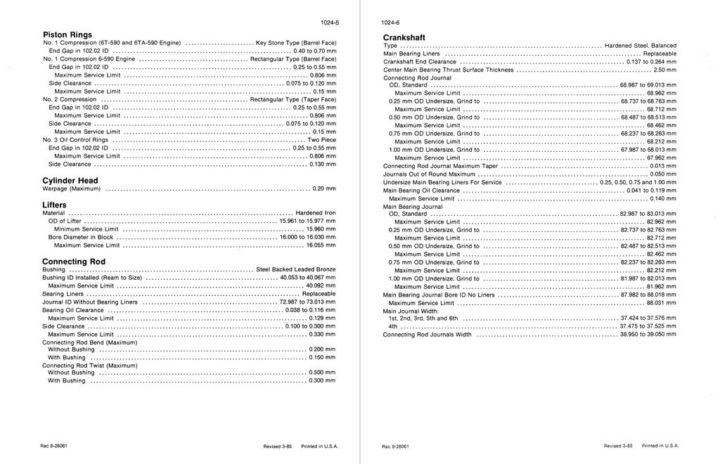
General Engine Specifications
Detailed Engine Specifications
2. ENGINE
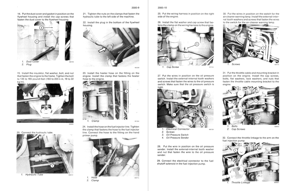
Engine Removal and Installation, Radiator Removal and Installation
Engine Accessories (Air Cleaner, Ether Injection, Mufflers, Turbocharger)
Stall Tests
Cylinder Head and Valve Train
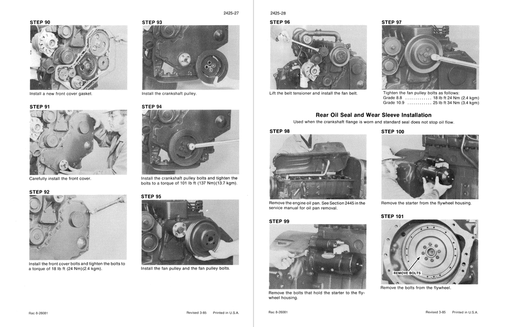
Cylinder Block, Crankshaft, Pistons, Rods, Camshaft, Oil Seals, Flywheel, and Crankshaft
Lubrication System
Cooling System
Turbocharger (Teardown)
Turbocharger Failure Analysis
3. FUEL SYSTEM
Fuel lines, Fuel Tank, and Engine Controls
Fuel System and Filters
Bosch Fuel Injection Pump, Drive Gear Timing
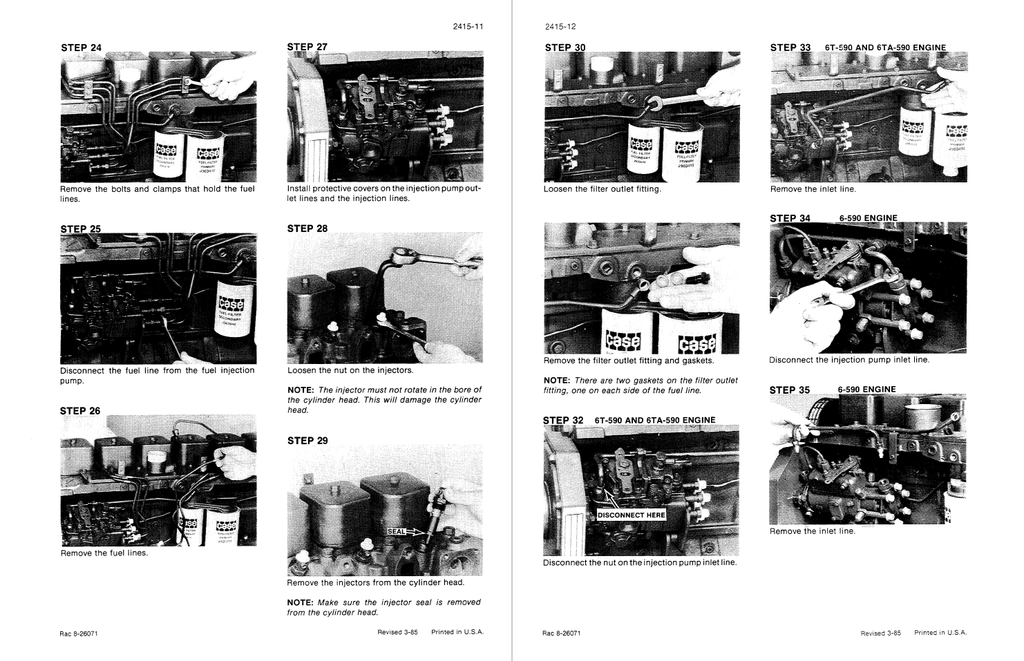
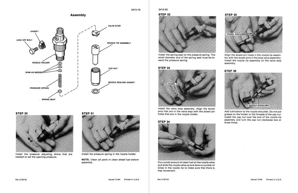
Fuel Injectors
4. ELECTRICAL SYSTEM
Removal and Installation of Electrical Components
Specifications and Troubleshooting
Wiring Diagrams
Instrument Cluster and Optional Gauges
Batteries
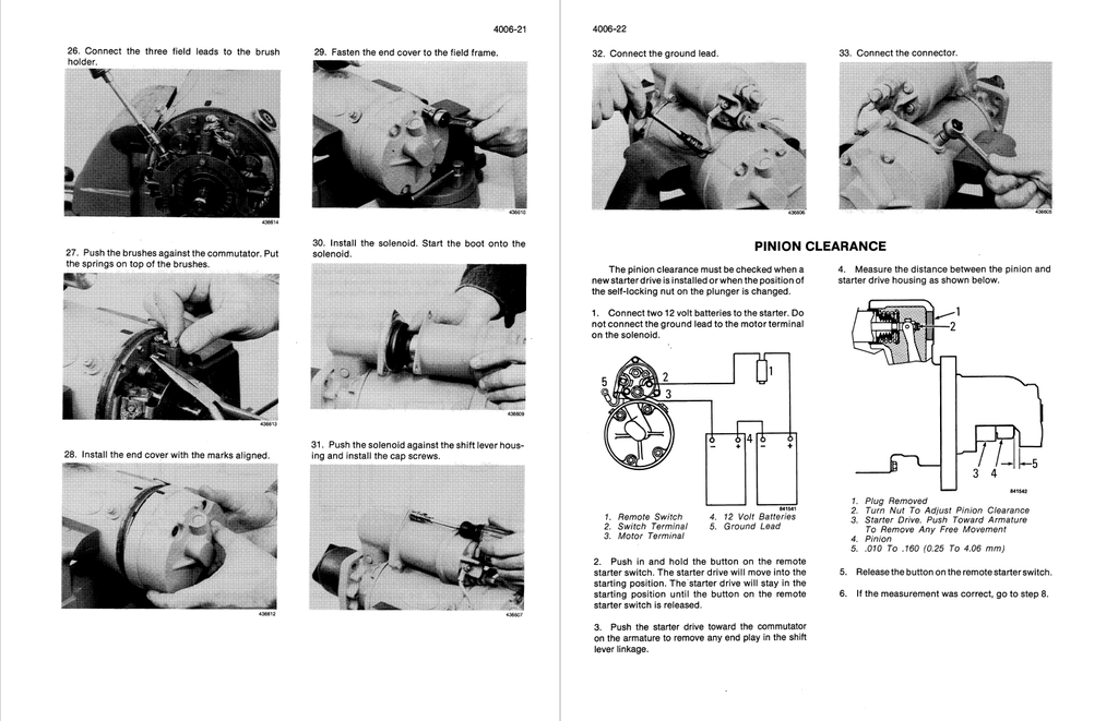
Starter and Starter Solenoid
40 Ampere Alternator
65 Ampere Alternator
5. STEERING
Removal and Installation of Steering
Components
Troubleshooting and Pressure Check
Hydraulic Schematic
Steering Control Valve
Flow Control Valve
Center Pivot
Auxiliary Steering Pump and Check Valve
Steering Cylinder
6. POWER TRAIN
Removal and Installation of Transmission, Axles, and Differentials
Maintenance
Troubleshooting and Pressure Checks
Torque Converter, Transmission, and Control Valve
Transmission Controls
Drive Shafts and Trunnions
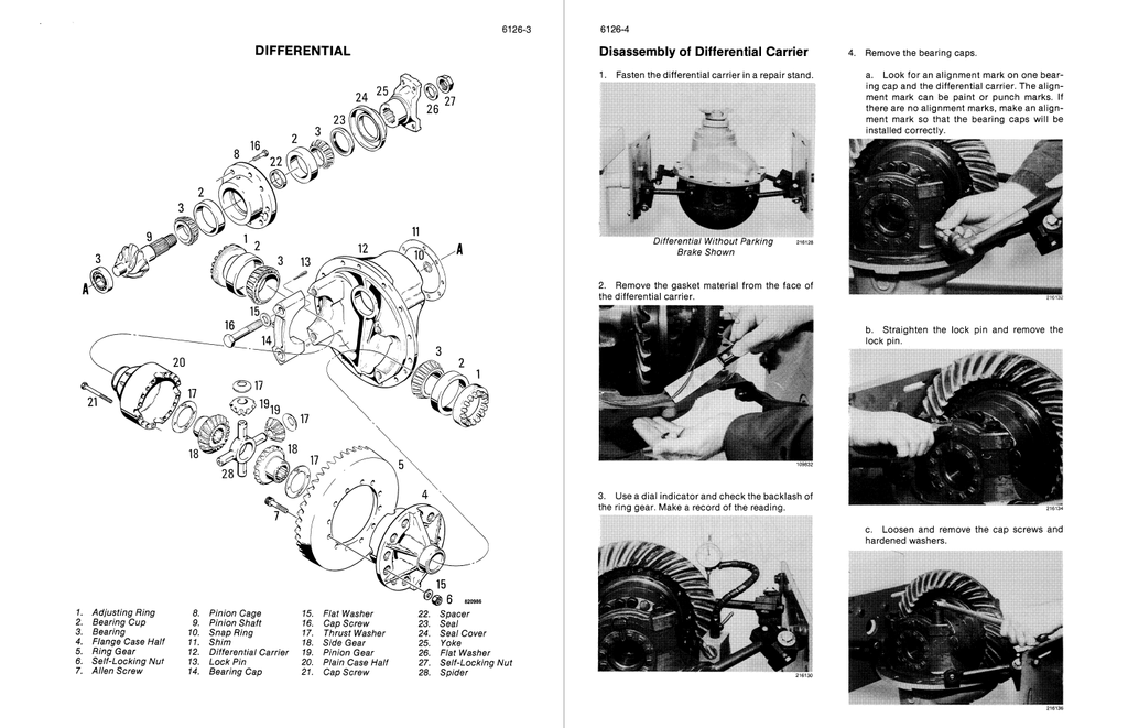
Differential and Planetary
Wheels and Tires
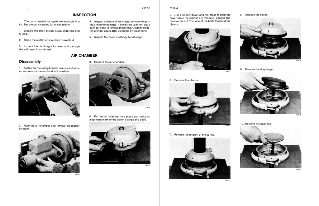
7. BRAKES
Removal and Installation of Brake System Components
Specifications, Diagram, Troubleshooting, Leakage Tests, and Adjustments
Air Compressor and Governor
Reservoirs and Relief Valve
Brake Valve
Brake Actuator
Pressure Reducing Valve and Pressure Protection Valve
Air Horn and Air Valve
Disc Brake
Parking Brake Actuator and Parking Brake Valve
8. HYDRAULIC
Removal and Installation of Hydraulic System Components
Maintenance
Specifications, Troubleshooting and Pressure Checks
Hydraulic Diagram
Cleaning the Hydraulic System
Pump
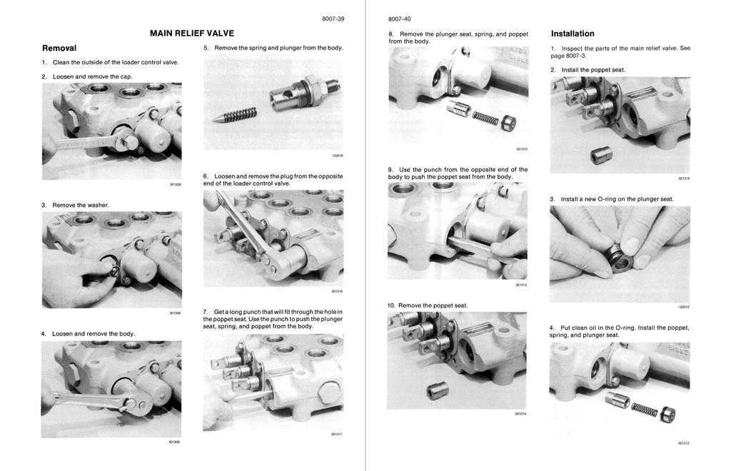
Loader Control Valve
Cylinders
9. MOUNTED EQUIPMENT
Air Conditioning Troubleshooting
Air Conditioning System
Loader
ROPS Cab and Canopy
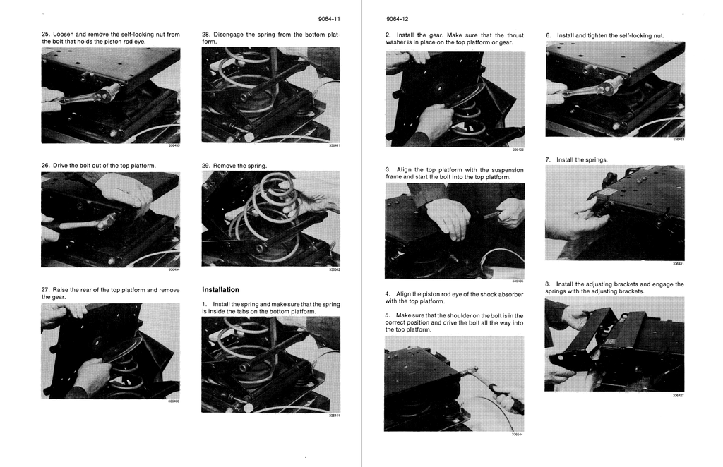
Seat and Seat Belts
Noise Control
REAR POCKET
Electrical Schematic - Front Harness
Electrical Schematic - Rear Harness
Electrical Schematic - Cab
Hydraulic Schematic