


Drott 35B, 40B, 50B B Series Crawler Excavator Service Manual S406173M2 English
Brand: CASE Construction / Drott
Product Range: Crawler Excavator
Publication Type: Service Manual
Equipment Model: 35B, 40B, 50B B Series Crawler Excavator
Serial Number: -
Publication Number: S406173M2
Issued: Printed in U.S.A. (Reprinted)
Language: English
Pages: 234
File Format: PDF Document
Additional Information: Procedures for maintaining and servicing all components and systems are provided with the exception of the engine. For Engine Repair, See the Engine Service Manual.
Introduction
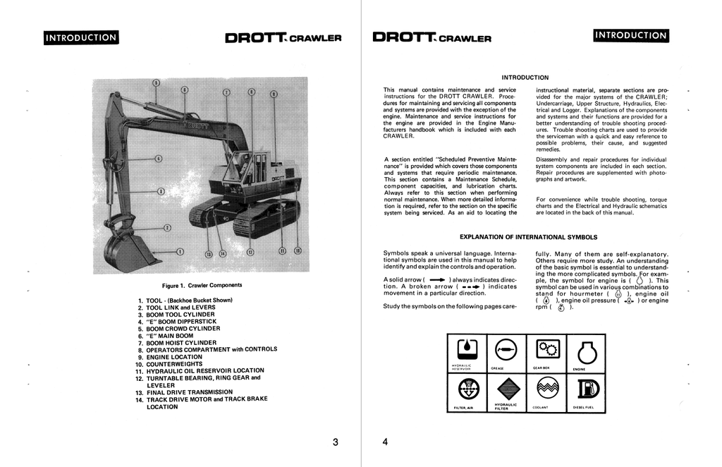
This manual contains maintenance and service instructions for the DROTT CRAWLER. Procedures for maintaining and servicing all components and systems are provided with the exception of the engine. Maintenance and service instructions for the engine are provided in the Engine Manufacturers handbook which is included with each CRAWLER.
A section entitled "Scheduled Preventive Maintenance" is provided which covers those components and systems that require periodic maintenance. This section contains a Maintenance Schedule, component capacities, and lubrication charts. Always refer to this section when performing normal maintenance. When more detailed information is required, refer to the section on the specific system being serviced. As an aid to locating the instructional material, separate sections are provided for the major systems of the CRAWLER; Undercarriage, Upper Structure, Hydraulics, Electrical and Logger. Explanations of the components and systems and their functions are provided for a better understanding of troubleshooting procedures. Troubleshooting charts are used to provide the serviceman with a quick and easy reference to possible problems, their cause, and suggested remedies.
Disassembly and repair procedures for individual system components are included in each section. Repair procedures are supplemented with photographs and artwork.
For convenience while troubleshooting, torque charts and the Electrical and Hydraulic schematics are located in the back of this manual.
Table of Contents
GENERAL
Table of Contents
Safety Precautions
Nomenclature
Introduction
Safety Symbols
Directional Reference
Parts and Service
SCHEDULED MAINTENANCE
Introduction
Cleaning Soundproofing Insulation
Spark Arrestors
Lubricant and Fluid Recommendations
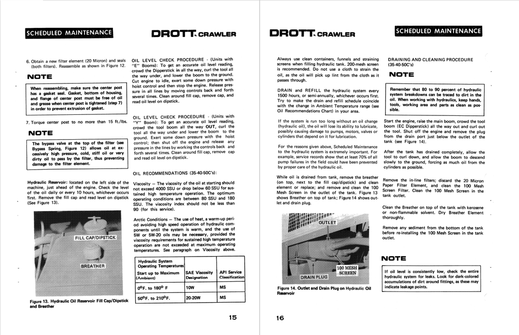
Hydraulic Oil Recommendations
Component Lubricants and Fluid Specifications
Hydraulic System Operating Pressures
Preventive Maintenance Schedule
Lubrication and Service Chart
Pictorial Listing of Grease Fitting Locations
Itemized Maintenance Instructions
Hydraulic Oil Filters
Hydraulic Reservoir
Hydraulic Oil Filter Screen (in-tank)
Swing Reduction Gearbox
Final Drive Transmissions
Turntable Open Gear
Engine
Engine Coolant
Oil Cooler
Batteries
Air Cleaner
Fuel Tank
CRAWLER UNDERCARRIAGE
General Description
Frames
Track Shoes
Track Rollers
Track Drive Motors
Track Drive Brake
Adjustment
Removal
Disassembly
Inspection and Repair
Mounting Track Brake to Final Drive Transmission
Final Drive Transmission
Trouble Shooting
Removal
Disassembly, Inspection and Re-assembly
Disassembly, Inspection and Re-assembly (40LC only)
Scheduled Maintenance (40LC only)
Track Adjustment Cylinder
Idler Wheel
Carbody and Carbody Leveler
Carbody Leveler Cylinder
Trouble Shooting - Tracks
UPPERSTRUCTURE
Replacing the Turntable Bearing
Removing the Upper
Checking Bearing Mounting Surface
Installing Bearing to Upper
Installing Upper to Lower
Torquing Procedure
Turntable Bearing Noise
Replacing Turntable on Machine without
Machined Bearing Mounting Surface
Swing Mechanism
Brake
Reduction Gearbox (2 piece output shaft)
Reduction Gearbox (1 piece output shaft)
Motor
Reduction Gearbox
Shimming the Gearbox
Disassembly and Repair
Installation
HYDRAULIC SYSTEM AND COMPONENTS
Introduction to Hydraulics
Troubleshooting
Flushing Procedure
Basic System Flow Diagrams
Main Tandem Pump
Description
Checking Gallonage Output
Removal
Disassembly, Inspection and Reassembly for:
Main Pump (used on 35 Crawlers)
Main Pump (used on 40 and 50 Crawlers)
Swing Motors
Installation of Pump Drive
Pump Breakin Procedure
Track Drive Motor (40BLC and 50LC)
Removal and Repair
Clam Rotary Actuator (270°)
Hydraulic Swivel
Valve Banks
Description
Removal
Power Beyond Plug
Deviation of Valve Body
Series Spool - Seal Replacement
Parallel Spool - Seal Replacement
Main Relief Valve
Relief Cartridge in Leveler Valve
Disassembly of Main Relief
Port Relief Valve
Swing Cross-Over Relief Valve
Track Brake Valve
Check Valves
Flow Regulators
Hydraulic Cylinders
Trouble Shooting Guides
Oil Flow Diagrams for:
Tool Cylinder Circuit
Crowd Cylinder Circuit
Hoist Cylinder Circuit
Leveler Cylinder Circuit
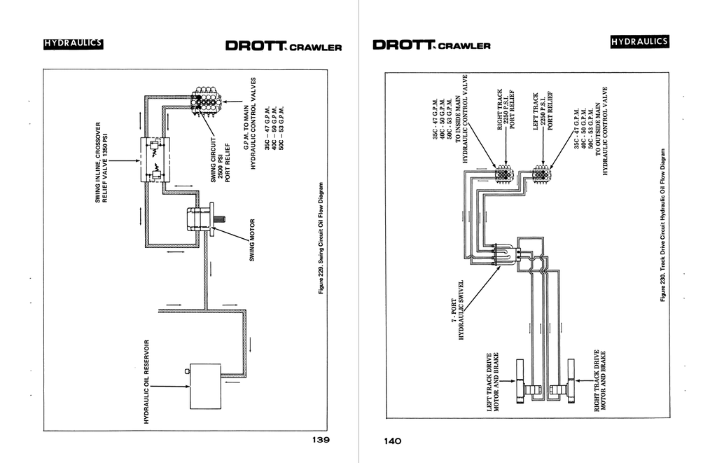
Swing Circuit
Track Drive Circuit
Track Brake and Drain Circuit
Feller/Buncher Circuit
Feller/Buncher Collector Circuit
ELECTRICAL
General Description
Battery Care
General Trouble Shooting
Trouble Shooting Guide
LOGGER
General Description
Feller/Buncher Maintenance
Feller/Buncher Collector
Rotary Cutter
MISCELLANEOUS
Torque Charts
Hydraulic Schematic
Electrical Schematic