

CASE Construction 430, 440 Skid Steer Loader Service Manual 6-78960 English
Official Manual Overview
Equip your workshop with the definitive factory Service Manual explicitly designed for the CASE 430 and 440 Skid Steer Loaders. This master-level guide delivers clinical troubleshooting and overhaul procedures for the entire hydrostatic drivetrain, featuring highly detailed tear-down specifications for the Sauer-Sundstrand Model 46 tandem axial piston pumps, as well as comprehensive breakdown steps for both single-speed and two-speed drive motors. Beyond extreme mechanical overhauls, it heavily focuses on the advanced Electronic Instrument Cluster (EIC), empowering technicians with the exact button-sequence codes to access locked "SETUP" menus, dynamically recalibrate engine preheat profiles (toggling between "CASE" and "ISM" systems), and override hydraulic lockouts directly from the cab. Please note: Following the manufacturer's strict publication structure, while engine removal and radiator installations are fully covered, internal diesel engine machining and fuel system repairs are relegated to a separate, dedicated engine manual.
- Brands: CASE Construction
- Equipment Type: Skid Steer Loader
- Manuals Type: Service Manual
- Machine Model: 430, 440
- Serial Number: All Serial Numbers
- Region: N/R
- Book Code: 6-78960
- Issued: Printed in U.S.A. February, 2005
- Language: English
- Pages: 524
- File Format: PDF (Searchable)
Selling Points
- Absolute Axial Piston Metrology: Rebuild the Sauer-Sundstrand Model 46 tandem pumps with zero guesswork. This manual dictates extreme internal machining tolerances, requiring the gear tip clearance between the inner and outer charge pump gears to be no greater than 0.13 mm (0.005 inch). Furthermore, it strictly mandates that gear width variations must be held between 0.05 and 0.06 mm (0.002 to 0.003 inch) to guarantee maximum volumetric efficiency.
- Dual-Displacement & Single-Speed Motor Overhauls: Whether your machine utilizes the standard or 2-Speed drive motors, this guide provides the clinical teardown sequences for both. It establishes the critical lockdown torque for the spring-applied brake cover plates at exactly 14 to 16 Nm (10 to 12 lb-ft), and defines the maximum brake release pressure at 1379 kPa (13.8 bar / 200 psi) to prevent catastrophic seal blowouts.
- Extreme Output Benchmarking: Validate your driveline’s structural health before tearing into the chassis. The hydrostatic performance matrix provides the ultimate torque parameters, requiring a healthy two-speed motor in Low Range to produce a massive 2019 Nm (1489.1 lb-ft) at relief pressure, and 1211.6 Nm (893.6 lb-ft) in High Range, allowing technicians to instantly isolate fluid degradation from mechanical wear.
Features & Highlights
- Dynamic Hydraulic Validation & Tooling: Equip your shop with factory-level flow testing doctrines. Specifying the use of the CAS-1804 Pressure Test Kit, the manual maps out the entire 3-spool loader control valve logic. It demands precise gear pump flow validation at three distinct load points: 97 bar, 124 bar, and 152 bar strictly at 2200 r/min, ensuring your lift and tilt circuits operate at peak breakout force.
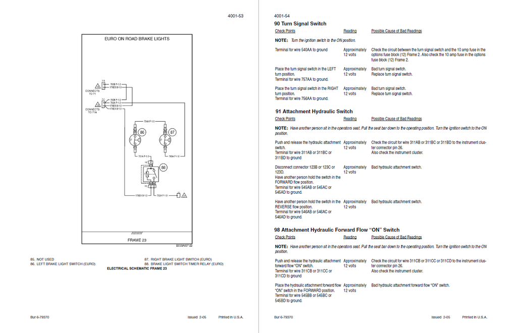
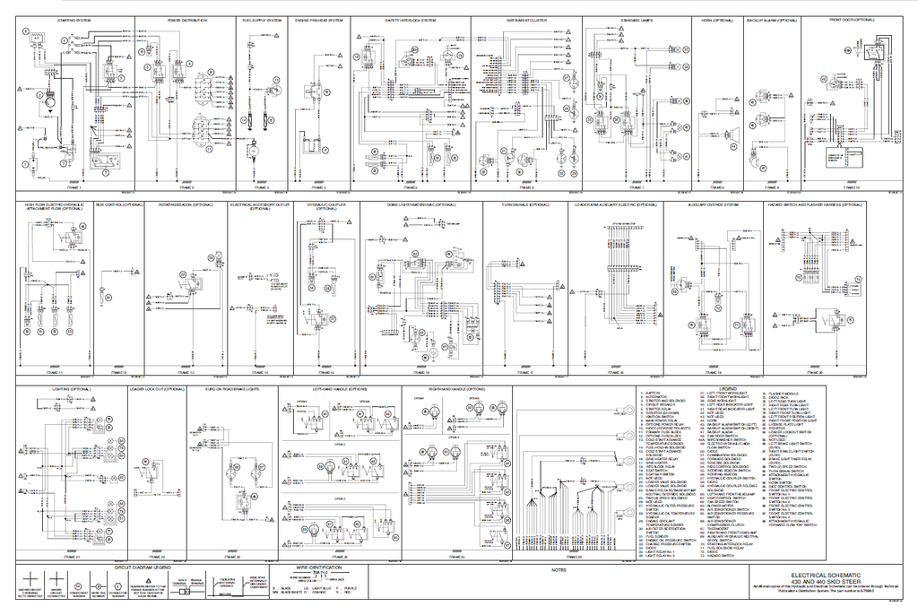
- Massive 26-Frame Electrical Topography: Untangle the complex skid steer harness with 26 master wiring frames and dozens of specific connector pinouts. Trace every circuit down to the cavity level—for instance, navigating Connector 71B (Euro) or probing the Safety Interlock System to verify exactly 12 volts on the 311F (T) wire when the seat bar is engaged.
- EIC Dashboard Engineering: Take full administrative control over the Electronic Instrument Cluster without requiring proprietary dealer software. The manual reveals the exact hidden push-button sequences to unlock the "SETUP" menu. Technicians can digitally recalibrate the engine preheat profiles between "CASE" and "ISM" configurations, or perform hard resets on engine hour telemetry.
Problem Solver
- Defeating "Crank-No Start" & Interlock Failures: When the starter engages but the fuel system refuses to fire, the troubleshooting tree bypasses the parts cannon. It directs you to test the fuel hold-in solenoid circuit, verifying voltage on the 602G (W) 1.0 wire at Connector 127A, cleanly isolating a failed starting interlock relay from a compromised EIC output.
- Eradicating Phantom Dashboard Alarms: Stop chasing imaginary engine failures. If the cluster falsely triggers a critical oil pressure warning, the electrical matrix guides you to probe the 255C (Y) circuit. It establishes that the switch must drop to 0 volts only if physical pressure falls below the 70 kPa (10 psi) threshold, proving whether the sensor has internally shorted.
- Curing Driveline Power Loss & Hesitation: If the machine stalls out under heavy pushing loads, the manual forces a logical progression of hydrostatic tests. By systematically checking the charge pressure and inspecting the physical condition of the tow valves, it prevents technicians from prematurely dismantling the $5,000 tandem pump when the issue might simply be a bypassing relief valve.
⚠️ Important Fitment & Coverage Note:As explicitly mandated by the manufacturer in the Section Index: "For Engine Repair - See Engine Service Manual 6-74500" and "For Fuel System Repair - See the Engine Service Manual 6-74500". This manual comprehensively details the engine extraction, radiator installation, and hydrostatic mating procedures, but it absolutely does not contain the internal machining, honing, or fuel injection pump rebuild procedures for the diesel engine block.
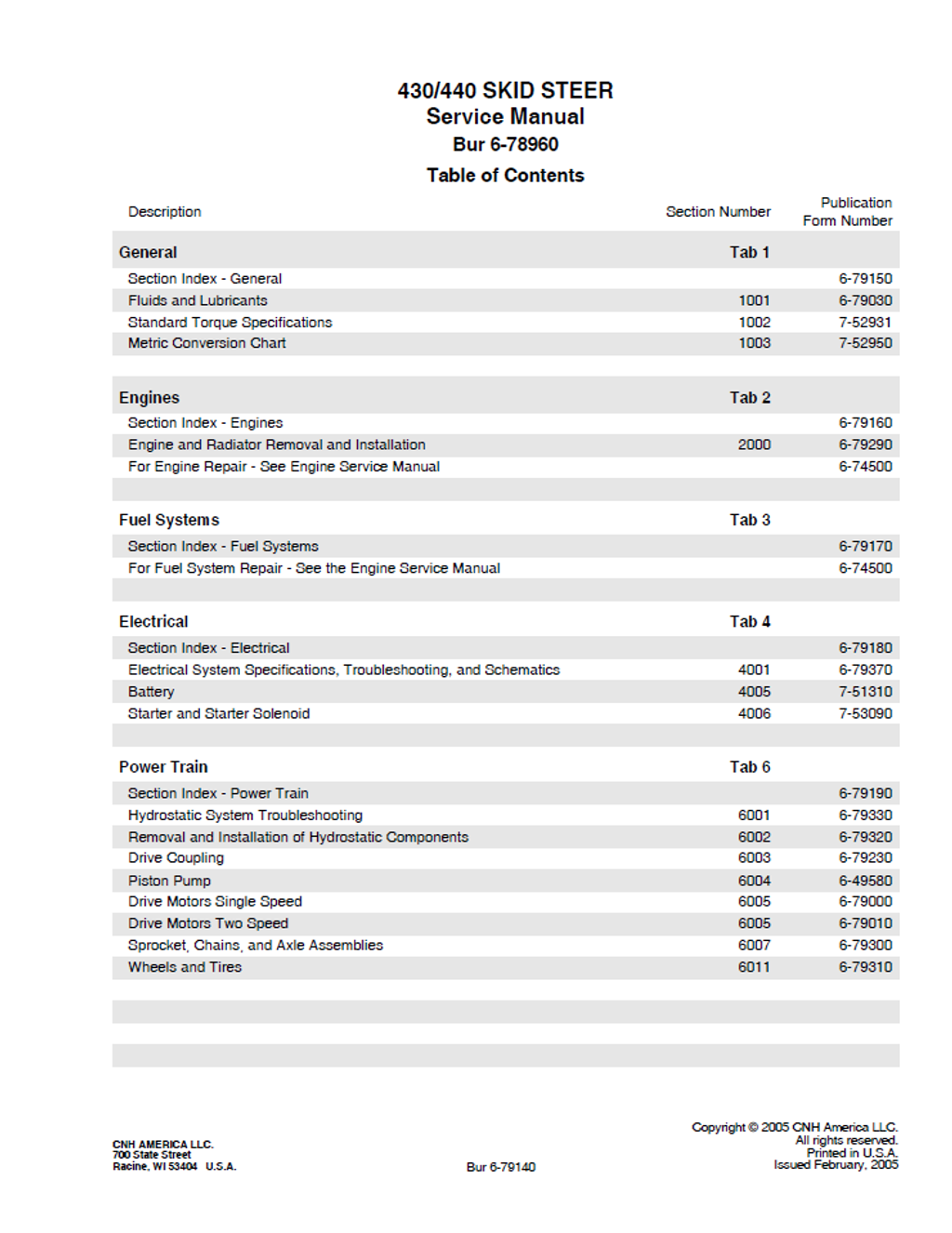
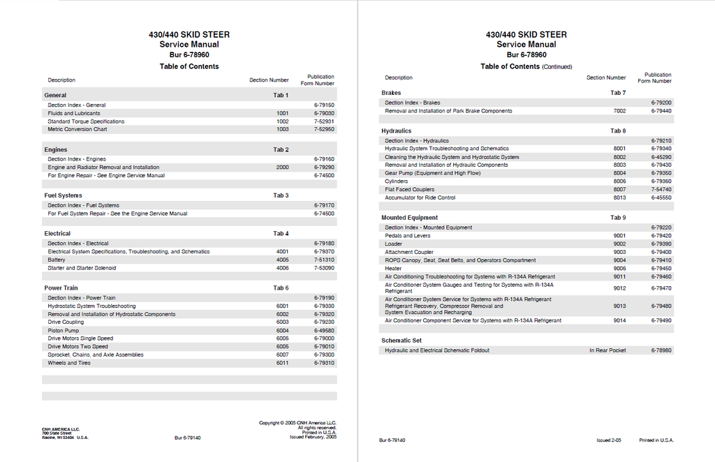
Table of Contents
- GENERAL
- Section Index - General
- Fluids and Lubricants
- CAPACITIES AND LUBRICANTS
- ENVIRONMENT
- ENGINE LUBRICATION
- Standard Torque Specifications
- Metric Conversion Chart
- ENGINES
- Section Index - Engines
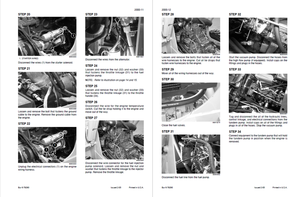
- Engine and Radiator Removal and Installation
- FUEL SYSTEMS
- Section Index - Fuel Systems
- ELECTRICAL
- Section Index - Electrical
- Electrical System Specifications, Troubleshooting, and Schematics
- GENERAL INFORMATION
- Circuit Diagram Legends
- Fuses
- TROUBLESHOOTING
- ELECTRICAL SCHEMATIC FRAME 1
- ELECTRICAL SCHEMATIC FRAME 2
- ELECTRICAL SCHEMATIC FRAME 3
- ELECTRICAL SCHEMATIC FRAME 4
- ELECTRICAL SCHEMATIC FRAME 5
- ELECTRICAL SCHEMATIC FRAME 6
- ELECTRICAL SCHEMATIC FRAME 7
- ELECTRICAL SCHEMATIC FRAME 8
- ELECTRICAL SCHEMATIC FRAME 9
- ELECTRICAL SCHEMATIC FRAME 10
- ELECTRICAL SCHEMATIC FRAME 11
- ELECTRICAL SCHEMATIC FRAME 12
- ELECTRICAL SCHEMATIC FRAME 13
- ELECTRICAL SCHEMATIC FRAME 14
- ELECTRICAL SCHEMATIC FRAME 15
- ELECTRICAL SCHEMATIC FRAME 16
- ELECTRICAL SCHEMATIC FRAME 17
- ELECTRICAL SCHEMATIC FRAME 18
- ELECTRICAL SCHEMATIC FRAME 19
- ELECTRICAL SCHEMATIC FRAME 20
- ELECTRICAL SCHEMATIC FRAME 21
- ELECTRICAL SCHEMATIC FRAME 22
- ELECTRICAL SCHEMATIC FRAME 23
- ELECTRICAL SCHEMATIC FRAME 24
- ELECTRICAL SCHEMATIC FRAME 25
- ELECTRICAL SCHEMATIC FRAME 26
- CONNECTORS SCHEMATIC FRAME 5
- Connector 57
- Connector 58
- Connector 59
- Connector 79
- Connector 80
- Connector 103
- Connector 127
- Connector 127A
- CONNECTORS SCHEMATIC FRAME 6
- Connector 8
- Connector 8A
- Connector 23 Instrument Cluster
- Connector 29
- Connector 30
- Connector 52
- Connector 52A
- CONNECTORS SCHEMATIC FRAME 7
- Connector 8
- Connector 8A
- Connector 32
- Connector 33
- Connector 34
- Connector 93
- Connector 96
- Connector 99
- CONNECTORS SCHEMATIC FRAME 8
- Connector 39 (Grey)
- CONNECTORS SCHEMATIC FRAME 10
- Connector 50A
- Connector 51
- Connector 51A
- Connector 65
- Connector 65A
- Connector 112
- Connector 113
- Connector 140
- Connector 140A
- Connector 141 Wiper/Washer Switch
- CONNECTORS SCHEMATIC FRAME 11
- Connector 70
- Connector 70A
- Connector 72
- Connector 81
- Connector 81B
- Connector 120
- Connector 121
- Connector 122
- Connector 123
- Connector 124
- CONNECTORS SCHEMATIC FRAME 12
- Connector 77
- CONNECTORS SCHEMATIC FRAME 13
- Connector 67
- Connector 68
- CONNECTORS SCHEMATIC FRAME 14
- Connector 71
- Connector 71A (Euro)
- CONNECTORS SCHEMATIC FRAME 15
- Connector 70
- Connector 70A
- Connector 73
- Connector 75
- Connector 76
- Connector 115
- Connector 115A
- CONNECTORS SCHEMATIC FRAME 16
- Connector 69
- Connector 117
- Connector 117A
- Connector 170
- Connector 171
- Connector 172
- Connector 174
- Connector 175
- Connector 176
- CONNECTORS SCHEMATIC FRAME 17
- Connector 66
- Connector 66A
- Connector 85
- Connector 86
- CONNECTORS SCHEMATIC FRAME 18
- Connector 49
- Connector 107
- Connector 138
- Connector 138A
- Connector 150
- Connector 150A
- CONNECTORS SCHEMATIC FRAME 19
- Connector 125
- Connector 127B
- Connector 127C
- Connector 128
- Connector 129
- Connector 130
- CONNECTORS SCHEMATIC FRAME 20
- Connector 66B
- Connector 66C
- Connector 92
- Connector 275
- Connector 276
- CONNECTORS SCHEMATIC FRAME 21
- Connector 86B
- Connector 226
- Connector 227
- Connector 228
- Connector 229
- Connector 230
- CONNECTORS SCHEMATIC FRAME 22
- Connector 50C
- Connector 50D
- Connector 119
- CONNECTORS SCHEMATIC FRAME 23
- Connector 71B (Euro)
- Connector 71C
- Connector 190 (Euro)
- CONNECTORS SCHEMATIC FRAME 24
- Connector 79B
- Connector 79C
- Connector 79D
- Connector 85A
- Connector 85D
- Connector 123B
- Connector 123C
- Connector 123D
- CONNECTORS SCHEMATIC FRAME 25
- Connector 39F
- Connector 39G
- Connector 39H
- Connector 49H
- Connector 77H
- Electronic Instrument CONSOLE (EIC)
- SWITCH PANEL
- Electronic Instrument PANEL (EIC)
- Electronic Instrument Cluster (EIC) Operating Instructions
- Special Feature Choices
- Detailed Description of Setup Items
- TROUBLESHOOTING ELECTRONIC INSTRUMENT CLUSTER (EIC)
- GENERAL INFORMATION
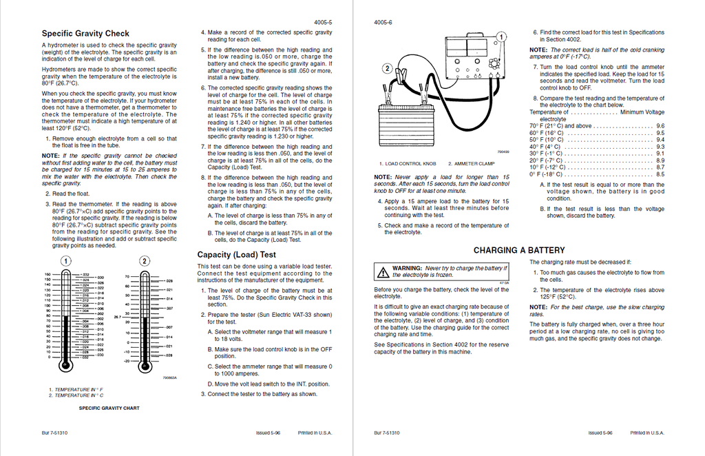
- Battery
- SAFETY RULES
- MAINTENANCE
- General Information
- Test Equipment
- Test Procedure
- DISASSEMBLY
- INSPECTION
- Starter and Starter Solenoid
- POWER TRAIN
- Section Index - Power Train
- Hydrostatic System Troubleshooting
- Removal and Installation of Hydrostatic Components
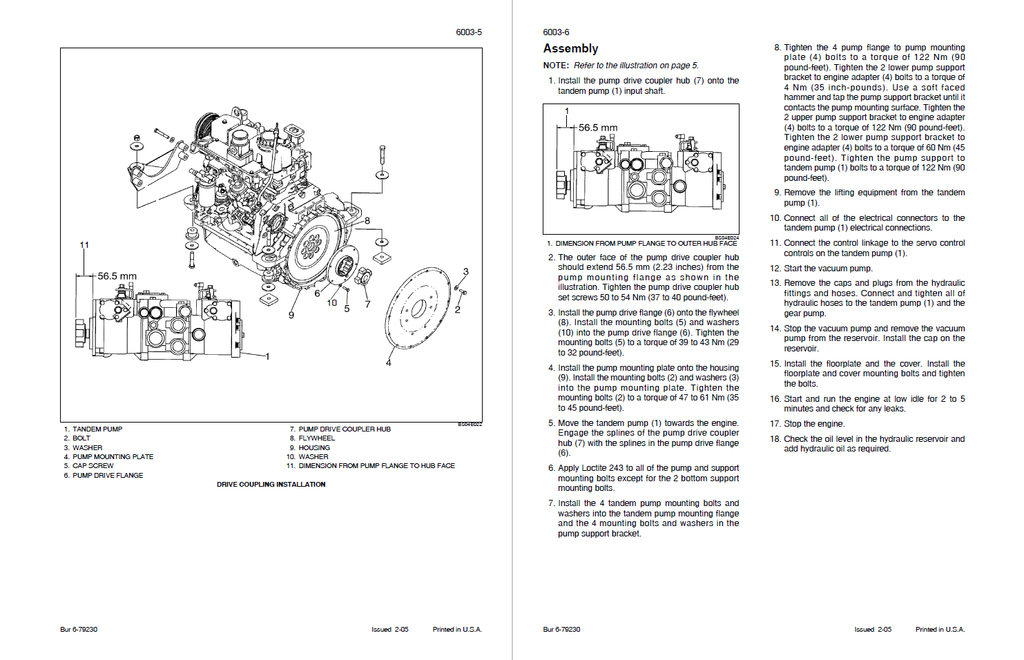
- Drive Coupling
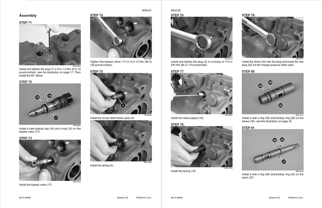
- Piston Pump
- Disassembly
- Inspection
- Assembly
- Drive Motors Single Speed
- Disassembly
- Inspection
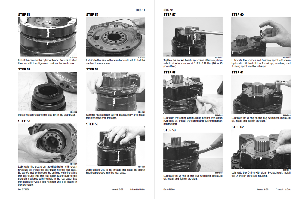
- Assembly
- Drive Motors Two Speed
- Sprocket, Chains, and Axle Assemblies
- BRAKES
- Removal and Installation of Park Brake Components
- SPECIFICATIONS
- Safety Rules
- Removal and Installation of Park Brake Components
- HYDRAULICS
- HYDRAULIC SYSTEM TROUBLESHOOTING AND SCHEMATICS
- SPECIFICATIONS
- SPECIAL TOOLS
- PRESSURE CHECKS
- 3 SPOOL LOADER CONTROL VALVE SCHEMATIC
- LOADER CONTROL VALVE
- METRIC MEASURE CHECK SHEET
- U.S. MEASURE CHECK SHEET
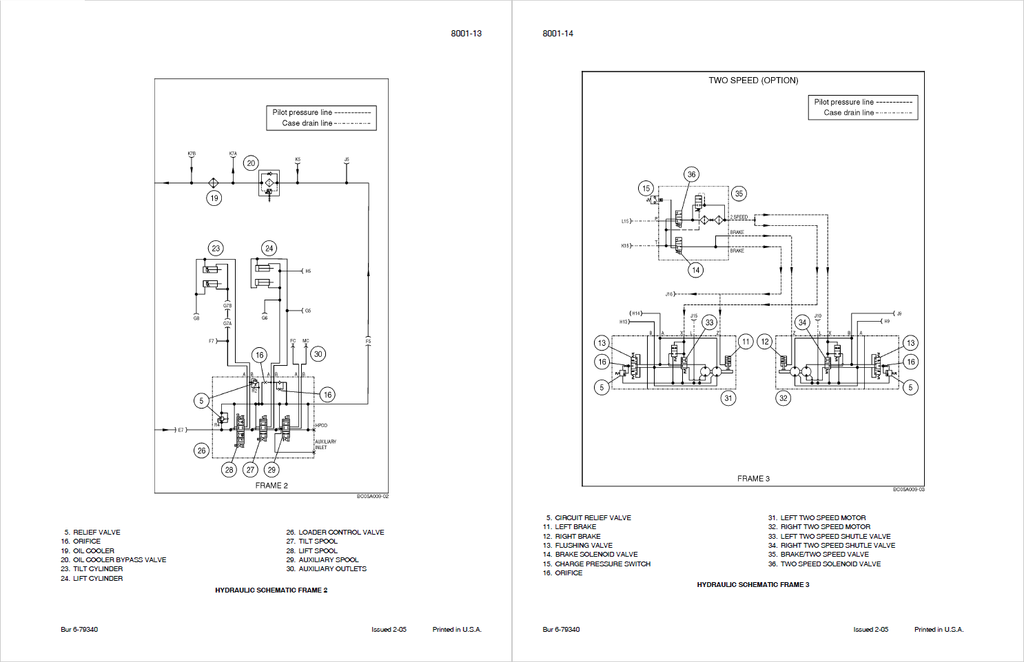
- HYDRAULIC SCHEMATIC FRAME 1
- HYDRAULIC SCHEMATIC FRAME 2
- HYDRAULIC SCHEMATIC FRAME 3
- HYDRAULIC SCHEMATIC FRAME 4
- HYDRAULIC SCHEMATIC FRAME 5
- HYDRAULIC SCHEMATIC FRAME 6
- HYDRAULIC SCHEMATIC FRAME 7
- HYDRAULIC SCHEMATIC FRAME 8
- Cleaning the Hydraulic System and Hydrostatic System
- Removal and Installation of Hydraulic Components
- Gear Pump (Equipment and High Flow)
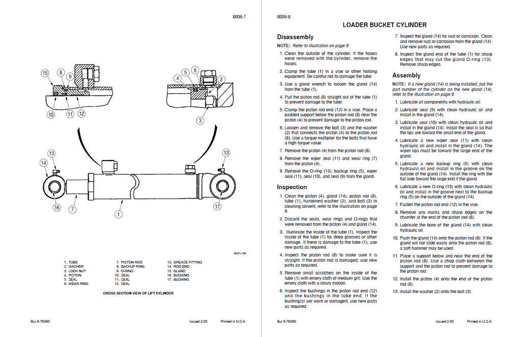
- Cylinders
- Flat Faced Couplers
- Accumulator for Optional Ride Control
- HYDRAULIC SYSTEM TROUBLESHOOTING AND SCHEMATICS
- MOUNTED EQUIPMENT
- PEDALS AND LEVERS
- SPECIFICATIONS
- THROTTLE CONTROL lever ADJUSTMENT
- ROPS Canopy, Seat, Seat Belts, and Operators Compartment
- Heater
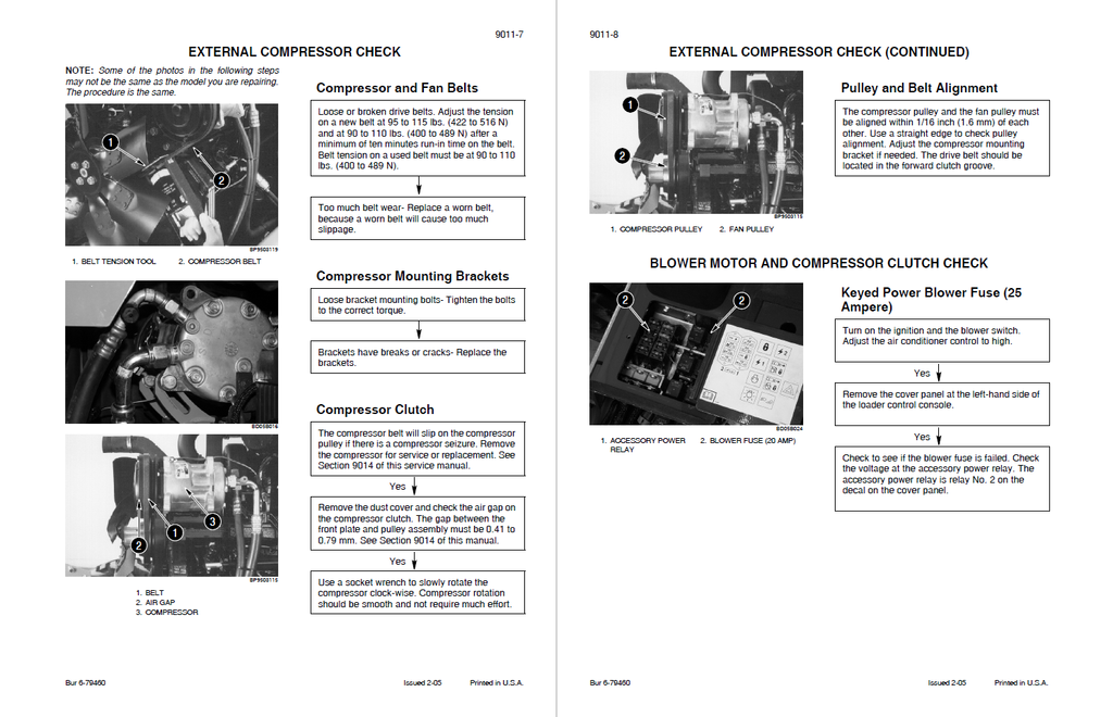
- Air Conditioning Troubleshooting for Systems with R-134A Refrigerant
- Air Conditioner System Gauges and Testing for Systems with R-134A Refrigerant
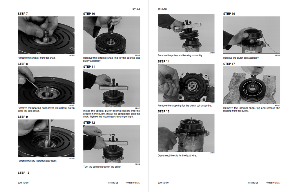
- Air Conditioner System Service for Systems with R-134A Refrigerant, Refrigerant Recovery, Compressor Removal and System Evacuation and Recharging
- Air Conditioner Component Service for Systems with R-134A Refrigerant
- PEDALS AND LEVERS
- SCHEMATICS
- Schematic Set Hydraulic and Electrical Schematic Foldout In Rear Pocket