

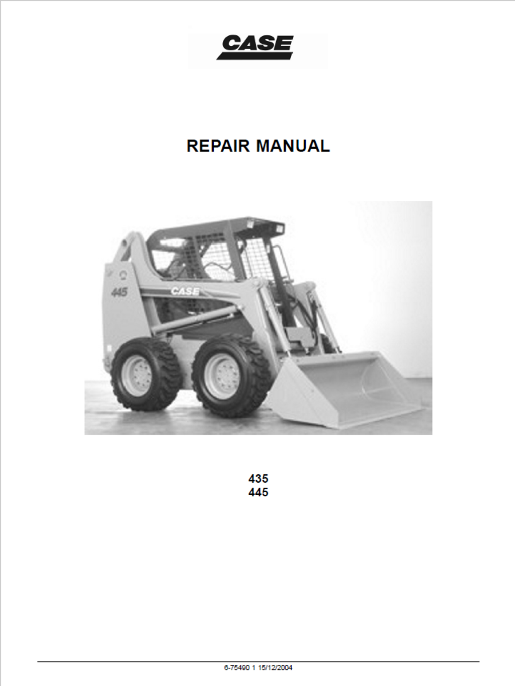
CASE Construction 435, 445 Skid Steer Loader Repair Manual 6-75490 English
Official Manual Overview
Dive into the mechanical core of the CASE 435 and 445 Skid Steers with this comprehensive official Repair Manual. Uniquely structured around the advanced ICE (Information Control Environment) coding system for rapid diagnostic data retrieval, this master guide provides uncompromising overhaul procedures for the entire powertrain and chassis. It delivers deep-level teardown and calibration protocols for the hydrostatic transmission, specifically targeting the Sauer-Danfoss M46 tandem axial piston pumps and Rexroth MCR05 radial piston motors. Crucially, unlike standard chassis manuals that omit internal engine repairs, this volume includes a complete, dedicated engine overhaul section for the F4CE0354A (334T/M2) 3-cylinder NEF turbocharged diesel engine. It details everything from connecting rod weight classifications (V, W, X) to exact crankshaft journal metrology and injection pump timing, making it the ultimate asset for complete skid steer restorations and advanced electro-hydraulic troubleshooting.
- Brands: CASE Construction
- Equipment Type: Skid Steer Loader
- Manuals Type: Repair Manual
- Machine Model: 435, 445
- Serial Number: All Serial Numbers
- Region: N/R
- Book Code: 6-75490
- Issued: Printed in U.S.A. 2004
- Language: English
- Pages: 912
- File Format: PDF (Searchable)
Selling Points
- Sauer-Danfoss Hydrostatic Metrology: Completely eliminate guesswork during tandem axial piston pump rebuilds. This manual exposes the exact internal clearances for the M46 pumps, demanding that gear tip clearance between the inner and outer gears must not exceed 0.13 mm (0.005 in), and gear width variations must be strictly held within a 0.05 to 0.06 mm (0.002 to 0.003 in) tolerance to prevent catastrophic pressure loss.
- Complete F4CE0354A Engine Machining: Unlike standard chassis guides, this volume contains a fully integrated engine overhaul section. It provides clinical diesel diagnostics, instructing mechanics to utilize the Motometer 75301430 tool for absolute compression testing, and details the exact bench-adjustment procedures for the rotary injection pump's L.D.A. device and automatic advance variator.
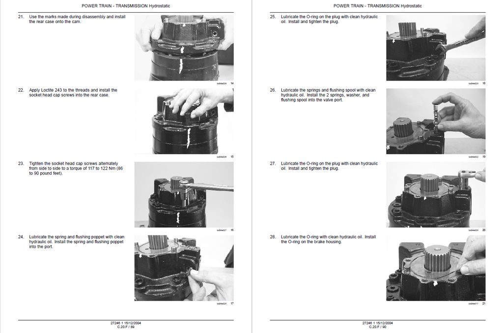
- Torque-to-Yield & Extreme Clamping Limits: Prevent structural separation under maximum payload. The manual enforces heavy-duty fastening standards, explicitly requiring the loader lift cylinder piston bolts to be locked down at 365 to 460 Nm (270 to 340 lb-ft). For the drive motor and brake assemblies, it mandates a strict torque-to-yield procedure of 122 Nm (90 lb-ft) plus an exact 60-degree rotation.
Features & Highlights
- EIC Dashboard "Hacking" & Setup Menus: Master the Electronic Instrument Cluster (EIC) without needing proprietary dealer laptops. The guide reveals the exact sequence to access hidden engineering menus, providing the factory "3671" access code to digitally unlock and reprogram engine hours, or manually override the transmission logic between "HYDRL" and "NOBRK" modes using the console push buttons.
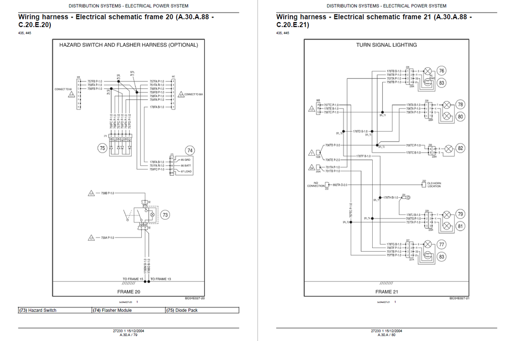
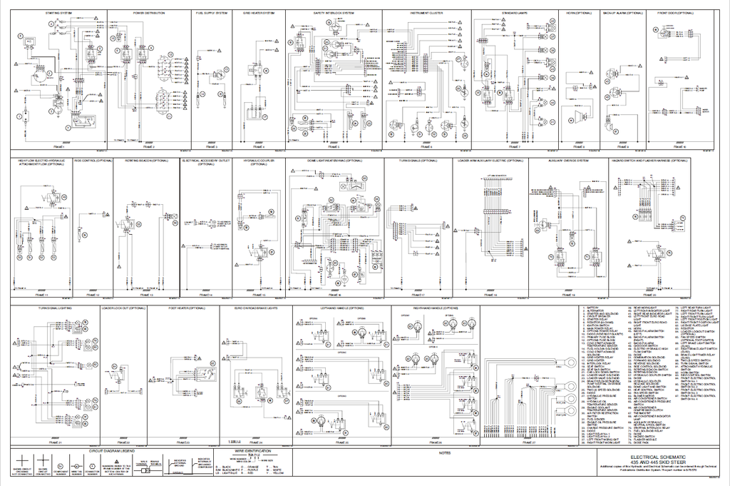
- Micro-Targeted Electrical Topography: Dominate the complex skid steer wiring harness through 26 dedicated frames of connector component diagrams. It traces every single cavity down to the exact pinout, such as verifying the hydraulic interlock relay by probing Connector 23 at Pin 19 (Wire 124B Red) and Pin 20 (Wire 200B Black/White for clean ground), ending blind electrical hunting.
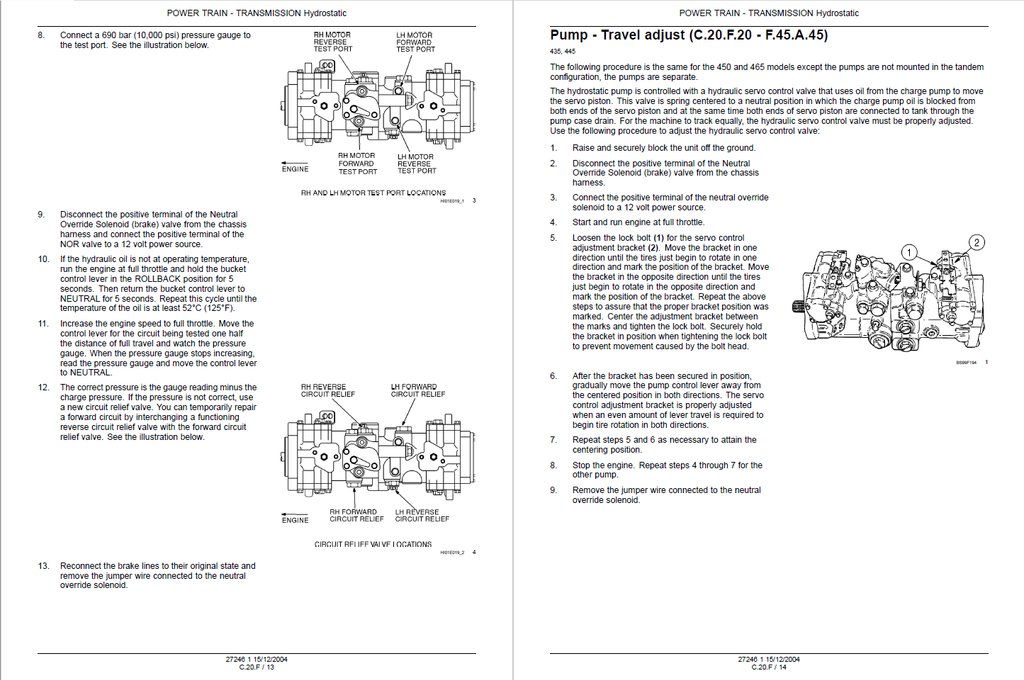
- OEM Pressure Benchmarking & Tooling: Equip your bay with the manufacturer's testing doctrines. It specifies the deployment of the CAS-1804 Pressure Test Kit to properly interrogate the charge pump and main relief valves. This ensures you can dynamically test the massive 6844 Nm (5049 lb-ft) capacity multiple-spring parking brake system directly at the axle output.
Problem Solver
- Defeating Hydraulic Lock-out & OPS Failures: When the skid steer refuses to move due to an Operator Presence System (OPS) fault, the manual bypasses the guesswork. It directs you to test the hydraulic brake solenoid circuit, requiring you to verify exactly 0 volts or 12 volts at the EIC Pin 8 (Wire 258A) while actively cycling the seat bar, isolating a failed sensor from a dead instrument cluster.
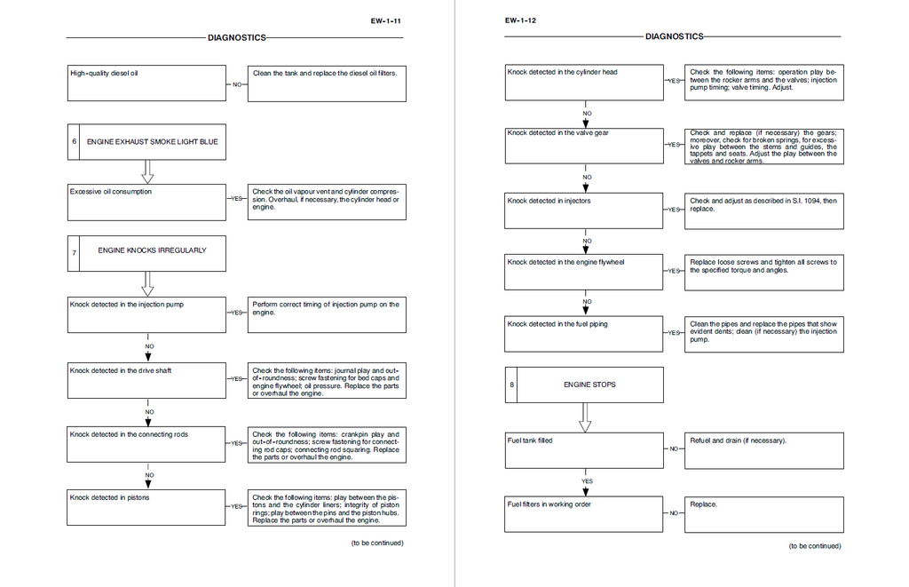
- Resolving Stubborn Exhaust Smoke Anomalies: Stop throwing expensive injectors at a smoking engine. The advanced diagnostic tree for black/dark grey exhaust smoke forces the technician to verify the fuel pump timing, check the static force-fit of the injection pump, and physically measure the tie-rod length on the mechanical throttle before opening the cylinder head.
- Curing Hydrostatic Drive Hesitation: If the machine experiences power loss or stops entirely under load, the troubleshooting matrix directly separates engine lag from transmission slip. It guides the technician through a sequential charge pressure test, preventing unnecessary hydraulic motor teardowns by first validating the bypass/tow valve integrity and tandem pump input speed.
⚠️ Important Navigation Note:Unlike traditional repair manuals that rely on sequential page numbers, this publication utilizes CASE's advanced ICE (Information Control Environment) alphanumeric coding system (e.g., A.10.A - F.10.A.10). Users must navigate the document using these specific function codes listed in the headers and footers to locate precise technical data, schematics, and teardown procedures.
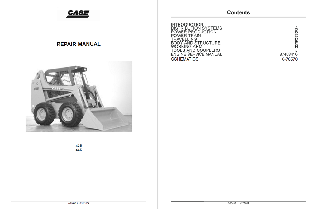
Table of Contents
- INTRODUCTION
- Basic instructions
- Torque
- Consumables
- Conversion factors
- DISTRIBUTION SYSTEMS
- PRIMARY HYDRAULIC POWER SYSTEM
- Technical Data
- Capacity
- General specification
- Special tools
- Relief valve - General specification
- Hydraulic pump - General specification
- Oil filter by-pass - General specification
- Functional Data
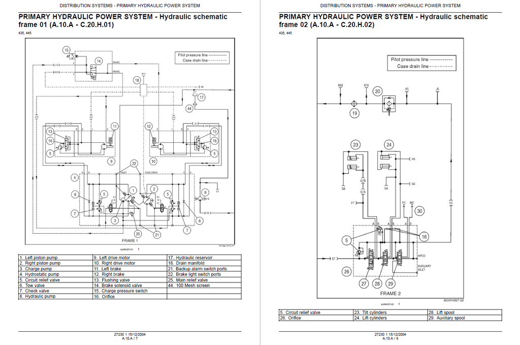
- Hydraulic schematic frame 01
- Hydraulic schematic frame 02
- Hydraulic schematic frame 03
- Hydraulic schematic frame 04
- Hydraulic schematic frame 05
- Hydraulic schematic frame 06
- Hydraulic schematic frame 07
- Hydraulic schematic frame 08
- Hydraulic pump - Sectional view
- Service
- Cleaning
- Decontaminating
- Relief valve - Flow test
- Relief valve - Pressure test
- Hydraulic pump - Flow test
- Hydraulic pump - Remove
- Hydraulic pump - Disassemble
- Hydraulic pump - Visual inspection
- Hydraulic pump - Assemble
- Hydraulic pump - Install
- Charge pump - Pressure test
- Reservoir - Apply vacuum
- Reservoir - Filling
- Oil filter - Remove
- Oil filter - Install
- Oil filter - Visual inspection
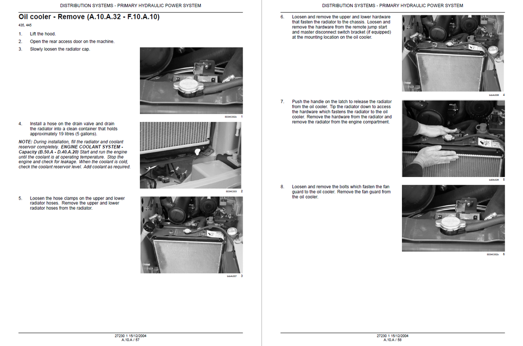
- Oil cooler - Remove
- Oil cooler - Install
- Diagnostic
- Sensing system Temperature sensor - Testing
- Sensing system Filter restriction sensor - Testing
- Technical Data
- SECONDARY HYDRAULIC POWER SYSTEM
- Technical Data
- Coupler - Special tools
- Service
- Flow test
- Cleaning
- Decontaminating
- Coupler - Disassemble
- Coupler - Assemble
- Oil cooler - Remove
- Oil cooler - Install
- Technical Data
- HIGH-FLOW HYDRAULIC POWER SYSTEM
- Service
- Cleaning
- Decontaminating
- Control valve - Remove
- Control valve - Install
- Hydraulic pump - Remove
- Hydraulic pump - Install
- Service
- ELECTRICAL POWER SYSTEM
- Technical Data
- Alternator - Torque
- Alternator - Service limits
- Battery - General specification
- Functional Data
- Alternator - Sectional view
- Connector - Component diagram
- Connector - Component diagram frame 01 through 26
- Wiring harness - Electrical schematic frame 01 through 27
- Service
- Battery - Remove
- Battery - Install
- Battery - Visual inspection
- Battery - Check
- Battery - Electrical test
- Battery - Charging
- Battery - Filling
- Diagnostic
- Fuse and relay box Relay - Testing
- Alternator - Testing
- Circuit breaker - Testing
- Connector - Testing
- Auxiliary power connection Outlet 1 - Testing
- Auxiliary power connection Outlet 2 - Testing
- Auxiliary fuse and relay box Relay - Testing
- Auxiliary fuse and relay box Power switch - Testing
- Auxiliary fuse and relay box Left power switch - Testing
- Technical Data
- LIGHTING SYSTEM
- Diagnostic
- Dome light Electrical light - Testing
- Front work light Electrical light - Testing
- Marker light Indicator lamp - Testing
- Marker light Switch - Testing
- Rear work light Electrical light - Testing
- Turn/hazard light Diode - Testing
- Turn/hazard light Flasher unit - Testing
- Turn/hazard light Turn switch - Testing
- Diagnostic
- HYDRAULIC COMMAND SYSTEM
- Functional Data
- Command Remote control lever - Exploded view
- Functional Data
- PRIMARY HYDRAULIC POWER SYSTEM
- POWER PRODUCTION
- ENGINE
- Service
- Remove
- Install
- Service
- FUEL AND INJECTION SYSTEM
- Technical Data
- Fuel tank - Capacity
- Fuel tank - General specification
- Service
- Throttle command Mechanical throttle - Tension adjust
- Diagnostic
- Sensing system Level sensor - Testing
- Technical Data
- AIR INTAKE SYSTEM
- Diagnostic
- Sensing system Air cleaner restriction - Testing
- Diagnostic
- ENGINE COOLANT SYSTEM
- Technical Data
- Capacity
- General specification
- Service
- Radiator - Drain fluid
- Radiator - Remove
- Radiator - Install
- Diagnostic
- Sensing system Coolant temperature - Testing
- Technical Data
- LUBRICATION SYSTEM
- Technical Data
- Capacity
- General specification
- Diagnostic
- Sensing system Oil pressure - Testing
- Technical Data
- STARTING SYSTEM
- Technical Data
- Engine starter - General specification
- Functional Data
- Engine starter - Sectional view
- Engine starter - Exploded view
- Service
- Engine starter - Electrical test
- Engine starter - Disassemble
- Engine starter - Visual inspection
- Engine starter - Assemble
- Engine starter - Preliminary test
- Engine starter - Grease
- Starter solenoid - Electrical test
- Diagnostic
- Engine starter - Testing
- Start control Start relay - Testing
- Start control Start switch - Testing
- Technical Data
- REPAIR MANUAL FOR NEF ENGINES (F4CE0354A OVERHAUL)
- Diagnostics
- Coding of source engines
- General engine features
- Assembling play - specifications
- Tightening torque
- Tools
- Graphic indications and symbols
- General remarks
- Description of main mechanic engine components
- Drive shaft
- Drive shaft seal rings
- Connecting rods
- Pistons
- Distributing shaft
- Valve control
- Cylinder head
- Valves and valve seats
- Valve guides
- Engine flywheel
- Auxiliary component drive
- Lubrication
- Heat exchanger
- Oil pump
- Oil sump
- Oil vapour recirculation
- Cooling
- Water pump
- Mechanic injection supply system
- Fuel filter
- Mechanic fuel pump
- Injection assembly
- Engine bench-overhaul
- Disassembling the engine
- Removal of compensating units
- Replacing the seal ring
- Repair work on cylinder cluster
- Checks and measurements
- Checking head supporting surface on cylinder unit
- Valve gear
- Distributing shaft
- Checking the pin alignment
- Bushings
- Replacing the bushings
- Tappets
- Mounting the tappets – Distributing shaft
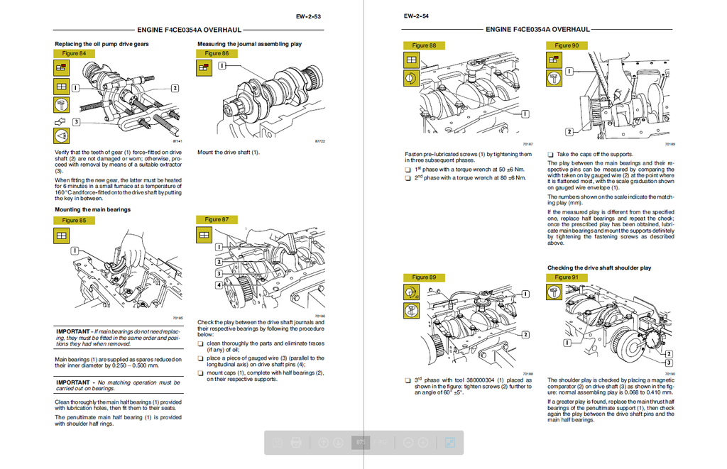
- Drive shaft
- Measuring the journals and crankpins
- Replacing the oil pump drive gears
- Mounting the main bearings
- Measuring the journal assembling play
- Checking the drive shaft shoulder play
- Connecting rod-piston assembly
- Pistons
- Measuring the piston diameter
- Gudgeon pins
- Conditions for correct pin/piston matching
- Piston rings
- Connecting rods
- Bushings
- Checking the connecting rods
- Checking the torsion
- Checking the flexion
- Fitting connecting rod-piston assembly
- Connecting rod-piston coupling
- Mounting the piston rings
- Mounting the connecting rod/piston assemblies in the cylinder liners
- Measuring the crankpin assembling play
- Checking piston protrusion
- Valve timing
- Engine flywheel
- Mounting the oil and water pump
- Mounting the water / oil heat exchanger
- Cylinder head
- Removing the valves
- Checking cylinder head wet seal
- Checking the cylinder head supporting surface
- Valves
- Valve descaling, check and grinding
- Checking clearance between valve stem and valve guide and valve centring
- Valve guide
- Valve seats
- Regrinding – replacing the valve seats
- Valve springs
- Fitting cylinder head
- Refitting the cylinder head
- Rocker arm assembly
- Mounting the injectors
- Rotary feed pump disassembly and assembly procedure
- Research of top dead centre by tool 380000988
- ENGINE
- POWER TRAIN
- POWER COUPLING Fixed coupling
- Technical Data
- Drive plate - Torque
- Service
- Pump drive - Remove
- Pump drive - Visual inspection
- Pump drive - Install
- Technical Data
- TRANSMISSION Hydrostatic
- Technical Data
- Special tools
- Pump - General specification
- Pump - Torque
- Motor - General specification
- Motor - Torque
- Functional Data
- External view
- Service
- Check
- Cleaning
- Startup test
- Travel adjust
- Relief valve - Pressure test
- Pump - Travel adjust
- Pump - Disassemble
- Pump - Assemble
- Pump Right hand pump - Disassemble
- Pump Right hand pump - Visual inspection
- Pump Right hand pump - Measure
- Pump Right hand pump - Assemble
- Pump Left hand pump - Disassemble
- Pump Left hand pump - Visual inspection
- Pump Left hand pump - Measure
- Pump Left hand pump - Assemble
- Pump - Remove
- Pump - Install
- Motor - Disassemble
- Motor - Assemble
- Motor - Remove
- Motor - Install
- Diagnostic
- Troubleshooting
- Technical Data
- POWER COUPLING Fixed coupling
- TRAVELLING
- FRONT AXLE
- Technical Data
- Torque
- Service
- Remove
- Install
- Disassemble
- Visual inspection
- Technical Data
- REAR AXLE
- Technical Data
- Torque
- Service
- Remove
- Install
- Disassemble
- Assemble
- Visual inspection
- Technical Data
- PARKING BRAKE Hydraulic
- Technical Data
- General specification
- Functional Data
- Control valve - Exploded view
- Service
- Remove
- Install
- Control valve - Disassemble
- Control valve - Assemble
- Braking device - Disassemble
- Braking device - Assemble
- Diagnostic
- Command Button - Testing
- Sensing system Pressure sensor - Testing
- Electrical control Solenoid - Testing
- Technical Data
- WHEELS AND TRACKS Wheels
- Technical Data
- Capacity
- General specification
- Torque
- Tire pressure
- Driven sprocket - Torque
- Drive sprocket - Torque
- Service
- Tire inflating
- Drive chain - Tension adjust
- Technical Data
- STEERING Mechanical
- Service
- Command - Adjust
- Service
- FRONT AXLE
- BODY AND STRUCTURE
- USER CONTROLS AND SEAT
- Functional Data
- Seat suspension system - Exploded view
- Console - Component diagram
- Instrument panel - Component diagram
- Instrument panel - Static description
- Service
- Seat - Remove
- Seat - Install
- Seat belt - Remove
- Seat belt - Install
- Instrument panel - Remove
- Instrument panel - Install
- Instrument panel - Electrical test
- Functional Data
- USER PLATFORM
- Service
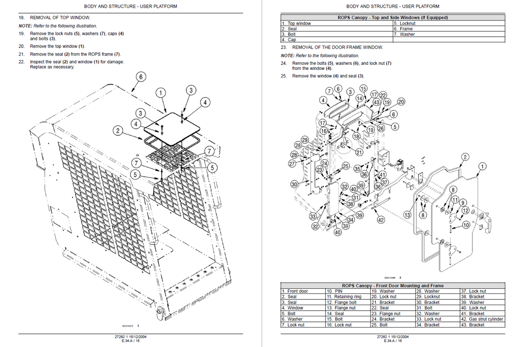
- ROPS - Remove
- ROPS - Install
- Door, window and windscreen - Remove
- Door, window and windscreen - Install
- Diagnostic
- Wiper system Motor - Testing
- Wiper system Switch - Testing
- Service
- ENVIRONMENT CONTROL Heating system
- Service
- Remove
- Install
- Heater - Remove
- Heater - Install
- Ventilation system - Remove
- Ventilation system - Install
- Diagnostic
- Heat command Fan speed switch - Testing
- Service
- ENVIRONMENT CONTROL Air-conditioning system
- Technical Data
- Special tools
- General specification
- Compressor - General specification
- Compressor - Capacity
- Compressor - Torque
- Compressor - Special tools
- Functional Data
- Dynamic description
- Compressor Magnetic clutch - Exploded view
- Service
- Connect
- Visual inspection
- Evacuate
- Discharging
- Charging
- Leakage test
- Remove
- Install
- Compressor - Remove
- Compressor - Filling
- Compressor - Install
- Compressor Belt - Measure
- Compressor Belt - Tighten
- Compressor Magnetic clutch - Disassemble
- Compressor Magnetic clutch - Electrical test
- Compressor Magnetic clutch - Assemble
- Condenser - Remove
- Condenser - Install
- Evaporator - Remove
- Evaporator - Install
- Receiver/drier - Replace
- Diagnostic
- Troubleshooting
- Testing
- Problem solving
- Compressor - Problem solving
- Technical Data
- SAFETY SECURITY ACCESSORIES Safety
- Service
- Operator presence system (OPS) Seat bar switch - Adjust
- Diagnostic
- Hydraulic lock-out Relay - Testing
- Hydraulic lock-out Electrovalve - Testing
- Hydraulic lock-out Diode - Testing
- Back up alarm Left switch - Testing
- Back up alarm - Testing
- Back up alarm Right switch - Testing
- Audible alert Switch - Testing
- Audible alert Horn - Testing
- Operator presence system (OPS) Seat swicth - Testing
- Operator presence system (OPS) Seat bar switch - Testing
- Service
- USER CONTROLS AND SEAT
- WORKING ARM
- SINGLE ARM Lift
- Technical Data
- Cylinder - Torque
- Accumulator - General specification
- Accumulator - Special tools
- Functional Data
- Cylinder - Sectional view
- Service
- Cleaning
- Decontaminating
- Remove
- Visual inspection
- Install
- Command Lever - Adjust
- Control valve - Remove
- Control valve - Install
- Ride control valve - Remove
- Ride control valve - Install
- Relief valve - Pressure test
- Relief valve - Flow test
- Cylinder - Disassemble
- Cylinder - Visual inspection
- Cylinder - Assemble
- Accumulator - Remove
- Accumulator - Install
- Accumulator - Charging
- Accumulator - Depressurising
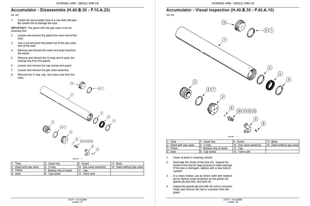
- Accumulator - Disassemble
- Accumulator - Visual inspection
- Accumulator - Assemble
- Accumulator - Pressure test
- Technical Data
- SINGLE ARM TOOL ATTACHMENT Tilt
- Technical Data
- Cylinder - Torque
- Relief valve - General specification
- Functional Data
- Cylinder - Sectional view
- Service
- Cleaning
- Decontaminating
- Control valve - Remove
- Control valve - Install
- Cylinder - Disassemble
- Cylinder - Visual inspection
- Cylinder - Assemble
- Relief valve - Pressure test
- Relief valve - Flow test
- Technical Data
- SINGLE ARM Lift
- TOOLS AND COUPLERS
- CARRYING Unarticulated tools
- Technical Data
- Tool Bucket - General specification
- Service
- Tool Cutting edge - Replace
- Technical Data
- COUPLING Hydraulic coupling
- Service
- Command valve Solenoid - Remove
- Command valve Solenoid - Install
- Control valve - Remove
- Control valve - Install
- Mechanical connector - Disassemble
- Mechanical connector - Assemble
- Mechanical connector - Visual inspection
- Non-return valve - Remove
- Non-return valve - Install
- Diagnostic
- Electrical control Coupler switch - Testing
- Service
- COUPLING Mechanical coupling
- Service
- Connector - Assemble
- Connector - Disassemble
- Connector - Visual inspection
- Service
- CARRYING Unarticulated tools