

CASE Construction 521D Wheel Loader Service Manual 6-40742 English
Official Manual Overview
This official factory Service Manual serves as the ultimate diagnostic and repair authority for CASE 521D wheel loaders, covering both standard Z-Bar and XT (tool carrier) linkage configurations. Tailored for advanced technicians, this heavy-duty guide heavily emphasizes electro-hydraulic diagnostics, featuring comprehensive electrical pin-outs, Information Center fault code matrices (including ZF Transmission ECM data), and precise flowmeter testing protocols (utilizing tools like the CAS-10280). A critical highlight of this publication is its extreme precision regarding production breaks: it provides completely distinct, dedicated tear-down procedures based on your machine's exact build (specifically isolating P.I.N. JEE0135500 and Below versus JEE0135501 and Above), ensuring absolute accuracy during front/rear axle and transmission overhauls. While internal diesel engine machining is relegated to a separate dedicated engine manual, this binder fully maps out engine extraction, stall tests, and the complete Powertrain and Powershift rebuilding process, making it an indispensable asset for major drivetrain and chassis restorations.
- Brands: CASE Construction
- Equipment Type: Wheel Loader
- Manuals Type: Service Manual
- Machine Model: 521D (Z-Bar and XT models)
- Serial Number: All Serial Numbers (Specifically covers P.I.N. JEE0135500 & Below, and JEE0135501 & Above)
- Region: N/R
- Book Code: 6-40742
- Issued: Printed in U.S.A. August, 2001 (Revised February, 2003)
- Language: English
- Pages: 1000
- File Format: PDF (Searchable)
Selling Points
- Deep-Level ZF Transmission & Clutch Diagnostics: Bypass the guesswork when dealing with drivetrain slippage. This manual cracks open the ZF Transmission ECM architecture, providing exact fault code resolutions. For example, it decodes Error 46182 (Slippage at clutch KR) and Error 46183 (Oil temperature at valve body above limit), dictating precise pressure checks and output speed sensor validations before you tear down the transmission.
- Factory Hydraulic & Stall Calibration Protocols: Prepare your shop with the exact diagnostic arsenal mandated by CASE. The guide specifies the use of the CAS-10280 Flowmeter and CAS-1904/1906 Pressure Fitting Kits to execute combined Torque Converter and Hydraulic Stall Tests (Test No. 1, 2, and 3), ensuring you can accurately isolate flow degradation between the implement pump and the hydrostatic drive.
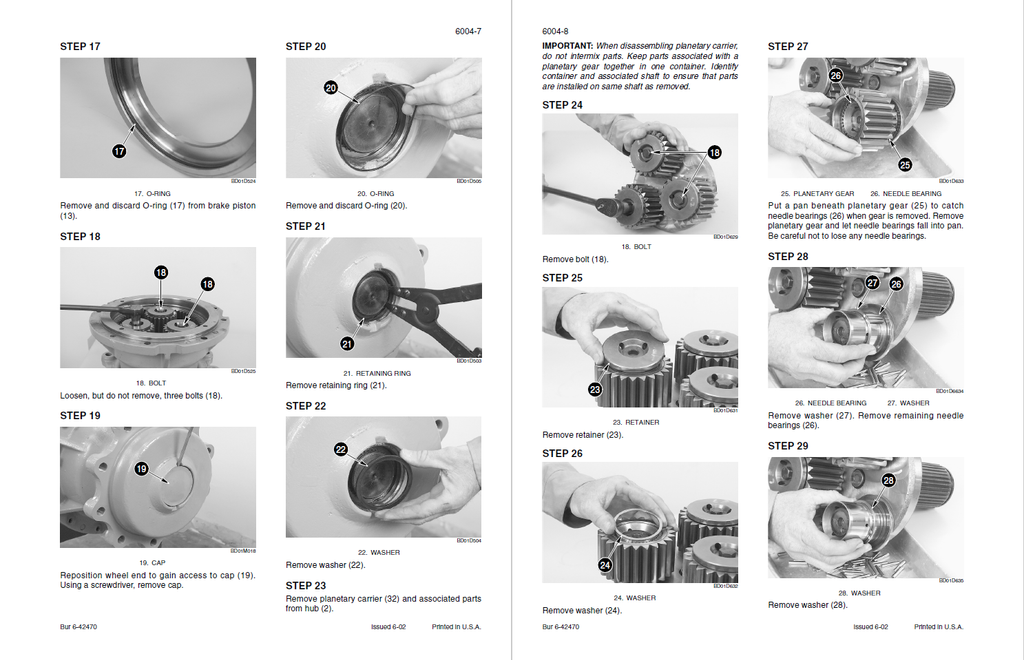
- Micrometric Axle & Gear Tooth Profiling: Rebuild the front and rear heavy-duty axles with clinical accuracy. The manual heavily details the ring and pinion gear tooth contact patterns (differentiating between Drive Side/Convex and Coast Side/Concave signatures), and instructs exactly when the pinion distance must be increased or decreased to prevent catastrophic differential failure.
Features & Highlights
- CAN-Bus & Six-Sheet Electrical Topography: Trace the machine's entire nervous system through massive, fold-out schematic posters (Sheets 1 through 6). It provides exhaustive connector pin-outs, allowing technicians to pinpoint the exact Y-0_5-SXL wire for CAN High at pin 50H, or track the Transmission Solenoid Valve Y6 directly to pin 25J, eliminating blind wire-chasing.
- On-Board Information Center Hacking: Unlock the hidden diagnostic menus of the loader's LCD Information Center. The guide instructs mechanics on how to navigate to Display Location 055 to reset the diagnostic stack, or scroll through locations 071 to 090 to retrieve historical fault codes, turning the dashboard into a powerful standalone diagnostic scanner.
- Strict Torque & Chemical Retaining Matrix: Maintain factory structural integrity under extreme loader breakout forces. The manual sets absolute clamping standards, requiring 9.5 Nm (84 lb-in) for distribution plate screws and 6 Nm (53 lb-in) for valve housing plugs, while strictly mandating the application of specific anaerobic compounds like Loctite® 518 (Gasket Eliminator) and Loctite® 271 for high-strength thread locking.
Problem Solver
- Eradicating Phantom Brake & Steering Alarms: Stop wasting hours on false dashboard warnings. If the monitor triggers Error 61900 or 61901, the troubleshooting tree directs you straight to the 1700 PSI (11,721 kPa) brake pressure switch or the 900 PSI (6250 kPa) redundant brake circuit, guiding you to test continuity and cycle the pedal 30 times rather than randomly replacing expensive control modules.
- Curing Transmission Shift Hesitation: When the machine stops or hesitates intermittently while shifting, the manual isolates the Powertrain logic. It guides you to inspect the Transmission Enable Switch circuits, verify the FNR (Forward-Neutral-Reverse) switch jumper at pin 26J, and execute a full transmission clutch calibration directly through the operator's console.
- Resolving Hydraulic Overheating (Error 72110): If the loader triggers a critical stop warning due to the hydraulic oil reaching 110°C (230°F) or greater, the diagnostic flowcharts prevent unnecessary cooler replacements. It forces the technician to first check the hydraulic filter restriction switch (circuit 31H) and test the temperature sender for a short circuit measuring less than 50 ohms.
⚠️ Important Fitment & Coverage Note:As explicitly stated by the manufacturer in the Section Index, "For Engine Repair, See the Engine Service Manual" and "For Fuel System Repair, See the Engine Service Manual." This manual thoroughly covers engine/radiator removal, powertrain installation, and engine stall testing, but does not include the internal machining, honing, or teardown of the diesel engine block or fuel injection pump.
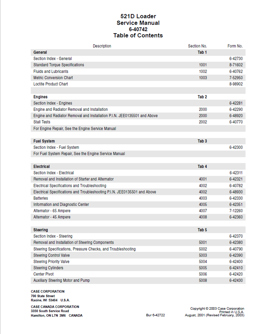
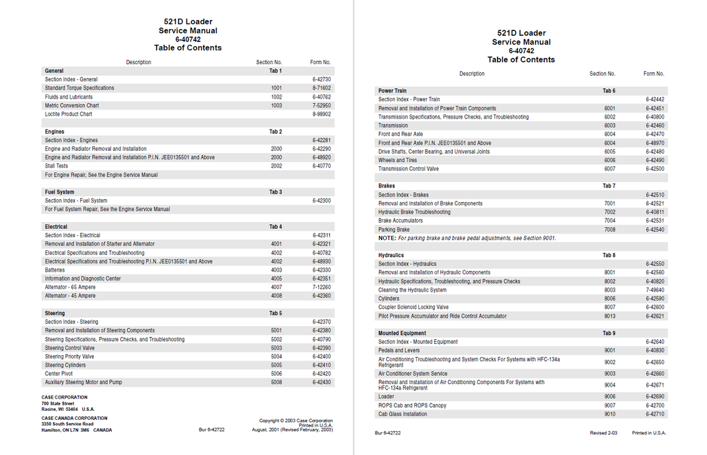
Table of Contents
- GENERAL
- Section Index - General
- Standard Torque Specifications
- TORQUE SPECIFICATIONS - DECIMAL HARDWARE
- TORQUE SPECIFICATIONS - METRIC HARDWARE
- Fluids and Lubricants
- Metric Conversion Chart
- CONVERSION FACTORS
- Metric to U.S.
- U.S. to Metric
- CONVERSION FACTORS
- Loctite Product Chart
- ENGINES
- Section Index - Engines
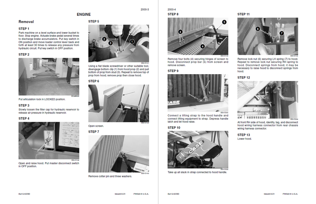
- Engine and Radiator Removal and Installation
- Engine and Radiator Removal and Installation P.I.N. JEE0135501 and Above
- ENGINE
- Removal
- Installation
- ENGINE
- Stall Tests
- FUEL SYSTEM
- Section Index - Fuel System
- ELECTRICAL
- Section Index - Electrical
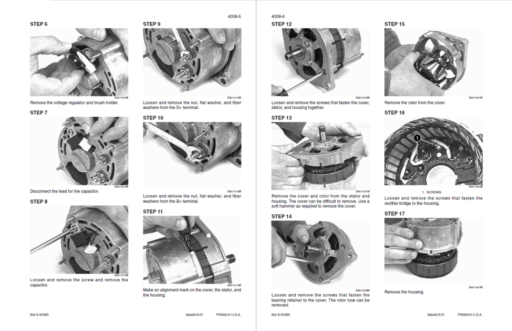
- Removal and Installation of Starter and Alternator
- STARTER
- P.I.N. JEE0135501 AND ABOVE
- Removal
- Installation
- P.I.N. JEE0135501 AND ABOVE
- STARTER
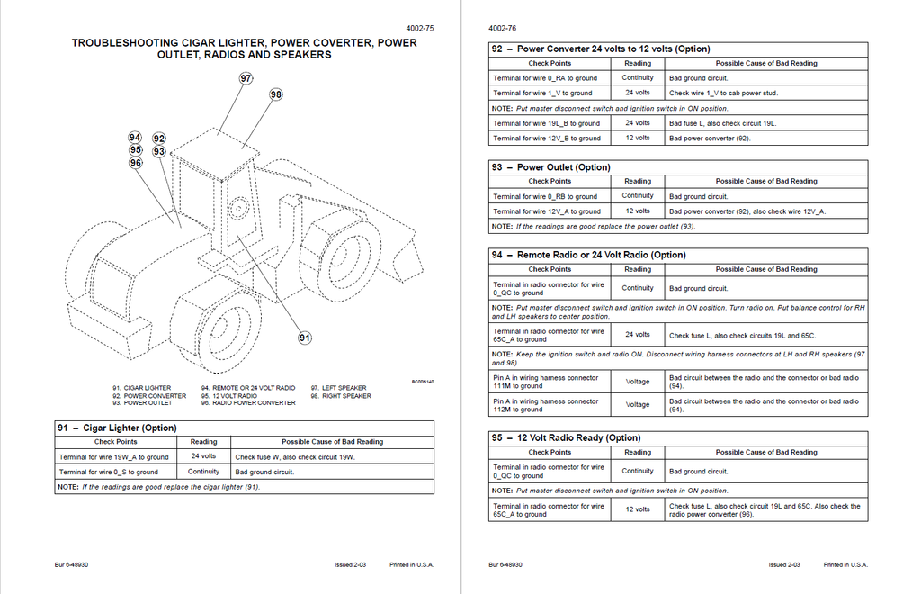
- Electrical Specifications and Troubleshooting
- SPECIFICATIONS
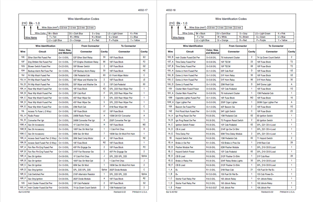
- ELECTRICAL WIRE IDENTIFICATION
- Wire Identification Codes
- Wire Identification From Connector To Connector
- UNDERSTANDING THE TROUBLESHOOTING TABLES
- LOCATING COMPONENTS ON THE SCHEMATIC POSTERS
- CONNECTORS
- INDEX
- Electrical Specifications and Troubleshooting P.I.N. JEE0135501 and Above
- SPECIFICATIONS
- ELECTRICAL WIRE IDENTIFICATION
- Wire Identification Codes
- Wire Identification From Connector To Connector
- UNDERSTANDING THE TROUBLESHOOTING TABLES
- LOCATING COMPONENTS ON THE SCHEMATIC POSTERS
- CONNECTORS
- INDEX
- Batteries
- SAFETY RULES
- SPECIAL TOOLS
- MAINTENANCE
- Information and Diagnostic Center
- INFORMATION AND DIAGNOSTIC CENTER
- Self-Test
- Power Circuit Test
- Indicators and Gauges
- Service Indicator Icon
- WARNING DISPLAYS
- Critical Warning Displays
- Non-Critical Warning Displays
- LCD DISPLAY
- Direction Selected
- Requested Gear
- Actual Gear
- Transmission Mode (Automatic or Manual)
- SYSTEM CHECKS
- Alarm Check
- Coolant Level Check
- Brake Pressure
- Secondary Steering Pressure Switch
- Park Brake Information Center Output Check
- Pilot Lockout Information Output Check
- Hydraulic Filter Restriction Switch Check
- Air Filter Restriction Switch Check
- Work Lights Check
- Air Conditioning Switch Check
- Transmission Filter Restriction Switch Check
- Requested Gear Check
- Operational Indicator Status
- Actual Gear Check
- Drive Line Shift Status
- Hourmeter Indicator Status
- Tachometer Indicator Status
- Service Indicator Status
- Movement Indicator Status
- Beacon Status
- Left Turn Indicator Status
- Right Turn Indicator Status
- Caution and Warning Master Indicator Lights Status
- Diagnostic Indicator Status
- Master Reset
- Park Brake Switch Check
- Redundant Brake Pressure Switch Check
- Service Brake Foot Switch Check
- Pilot Lockout Switch Check
- SETTINGS, DIAGNOSTICS, AND FAULT CODES
- Programming the Information Center
- DISPLAY LOCATIONS
- Display Location 047
- Minimum Gear Selection
- Maximum Gear Selection
- Gear Range Read Only
- Reset Diagnostic Stack for Locations 071 through 090
- Service Interval Hours
- Fault Code Status
- ZF Transmission ECM Part Number (1st part)
- ZF Transmission ECM Part Number (2nd part)
- Information Center Software Revision Number
- LED Duty Cycle
- LCD Duty Cycle
- Internal Information Center Temperature
- Entry Code for Accessing Test Mode Locations 100 to 199
- Display Location Numbers 131 - 139 Reserved for Speedometer Calibration
- Temporary Fault Code Status
- Display Location Number 197 Reserved for Manufacturing Data
- Display Location Number 199 Reserved for Manufacturing Data
- DISPLAY LOCATION NUMBERS AND DESCRIPTIONS
- FAULT CODES
- INDEX
- INFORMATION AND DIAGNOSTIC CENTER
- Alternator - 65 Ampere
- SPECIFICATIONS
- Alternator - 45 Ampere
- STEERING
- Section Index - Steering
- Removal and Installation of Steering Components
- Steering Specifications, Pressure Checks, and Troubleshooting
- Steering Control Valve
- Steering Priority Valve
- Disassembly
- Cleaning and Inspection
- Assembly
- Steering Cylinders
- Center Pivot
- Auxiliary Steering Motor and Pump
- Disassembly
- Inspection
- Assembly
- POWER TRAIN
- Section Index - Power Train
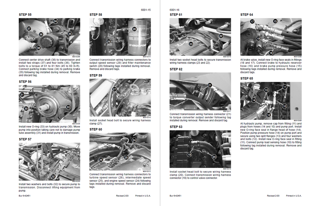
- Removal and Installation of Power Train Components
- Transmission Specifications, Pressure Checks, and Troubleshooting
- Transmission
- Front and Rear Axle
- Cleaning and Inspection
- Front and Rear Axle P.I.N. JEE0135501 and Above
- Drive Shafts, Center Bearing, and Universal Joints
- Wheels and Tires
- Transmission Control Valve
- Disassembly
- Inspection
- Assembly
- BRAKES
- Section Index - Brakes
- Removal and Installation of Brake Components
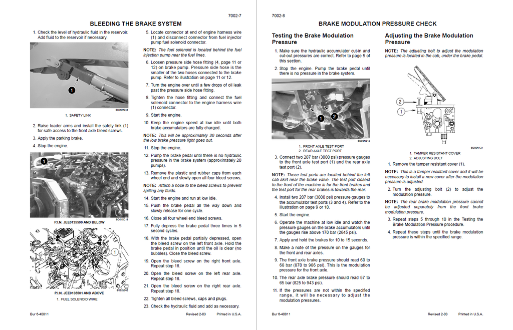
- Hydraulic Brake Troubleshooting
- Brake Accumulators
- SPECIAL TOOL
- DISCHARGING THE NITROGEN CHARGE ON AN ACCUMULATOR
- BRAKE ACCUMULATORS
- Disassembly
- Inspection
- Assembly
- Parking Brake
- PARKING BRAKE
- Removal and Disassembly
- Inspection
- Assembly and Installation
- PARKING BRAKE
- HYDRAULICS
- Section Index - Hydraulics
- Removal and Installation of Hydraulic Components
- Hydraulic Specifications, Troubleshooting, and Pressure Checks
- Problems in All Circuits
- Problem in All Loader Circuits
- Problem in the Braking Circuit
- Problem in a Single Loader Circuit
- Problem in the Steering Circuit
- Problem in the Ride Control
- Cleaning the Hydraulic System
- PORTABLE FILTER
- GENERAL INFORMATION
- Cylinders
- Coupler Solenoid Locking Valve
- Pilot Pressure Accumulator and Ride Control Accumulator
- PILOT PRESSURE ACCUMULATOR P.I.N. JEE0135500 AND BELOW
- Disassembly
- Inspection
- Assembly
- PILOT PRESSURE ACCUMULATOR P.I.N. JEE0135500 AND BELOW
- MOUNTED EQUIPMENT
- Section Index - Mounted Equipment
- Pedals and Levers
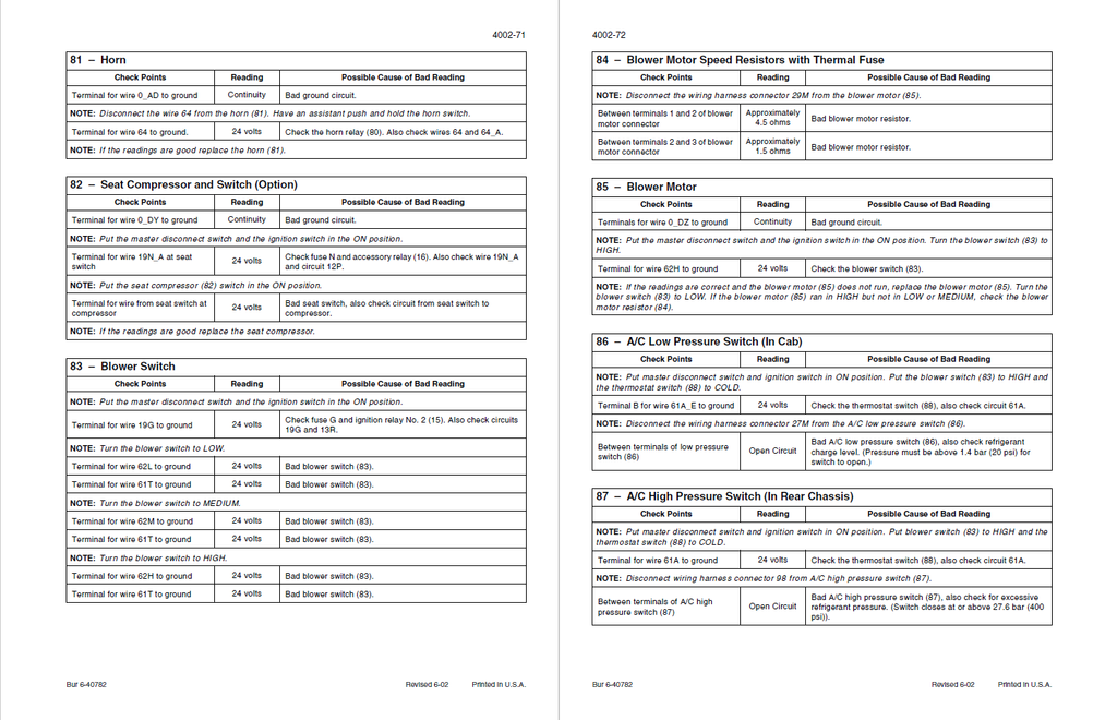
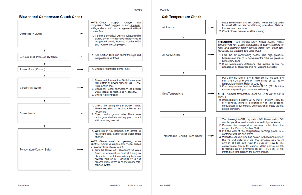
- Air Conditioning Troubleshooting and System Checks For Systems with HFC-134a Refrigerant
- SAFETY PROCEDURES
- OPERATION
- TROUBLESHOOTING
- Air Conditioner System Service
- Removal and Installation of Air Conditioning Components For Systems with HFC-134a Refrigerant
- P.I.N. JEE0135500 and Below
- P.I.N. JEE0135501 and Above
- COMPRESSOR INSTALLATION
- P.I.N. JEE0135500 and Below
- P.I.N. JEE0135501 and Above
- Loader
- ROPS Cab and ROPS Canopy
- Cab Glass Installation
- SCHEMATICS
- Electrical Schematic Foldouts and Hydraulic Schematic Foldout
- SHEET 1 - POWER CONTROL AND DISTRIBUTION
- SHEET 2 - TRANSMISSION CONTROLS
- SHEET 3 - INSTRUMENT CLUSTER
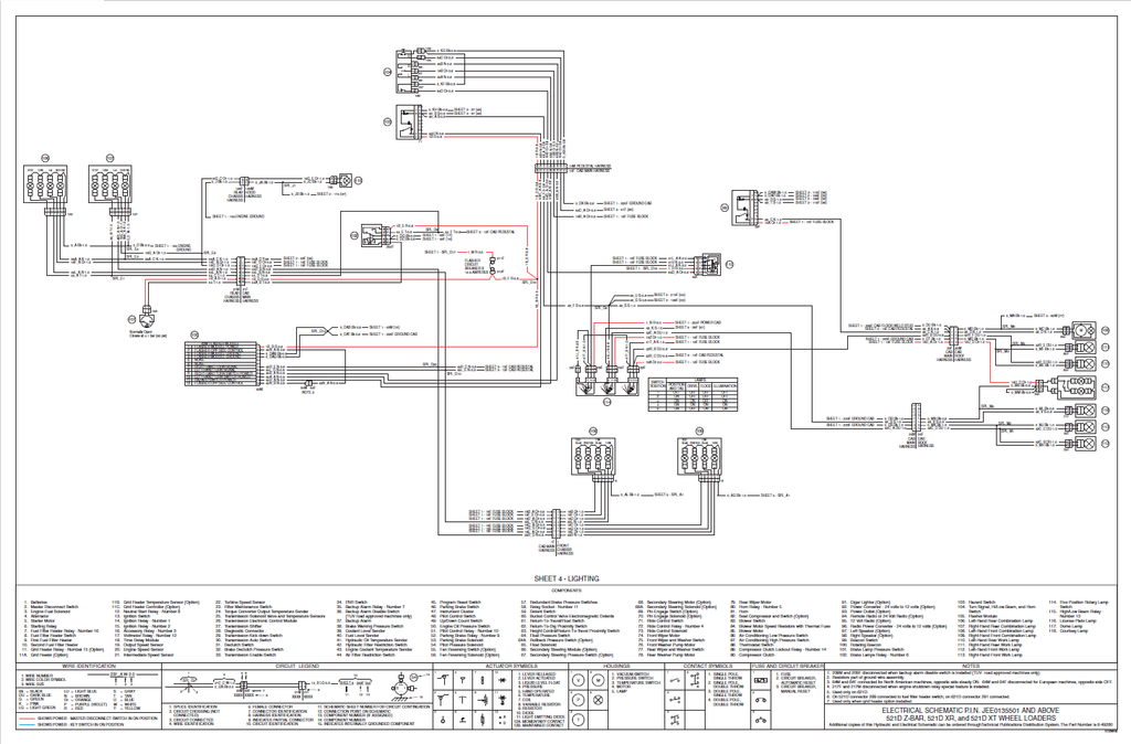
- SHEET 4 - LIGHTING
- SHEET 5 - MACHINE CONTROLS
- SHEET 6 - OPTIONS
- Electrical Schematic Foldouts and Hydraulic Schematic Foldout P.I.N JEE0135501 and Above
- Electrical Schematic Foldouts and Hydraulic Schematic Foldout