

CASE Construction 621D Wheel Loader Service Manual 6-42964 English
Official Manual Overview
This factory Service Manual delivers the definitive technical blueprint for overhauling, calibrating, and troubleshooting the CASE 621D wheel loaders, comprehensively covering both the standard Z-Bar and XT linkage configurations. Engineered for professional technicians, this document features a rigorous dual-track structure, distinctly separating service protocols and electrical schematics for machines built prior to and after P.I.N. JEE0135501. It boasts an exceptionally deep dive into the onboard Information and Diagnostic Center, instructing mechanics on how to hack into hidden menus to extract temporary fault codes, access the ZF Transmission ECM data, and perform dynamic clutch calibrations directly from the operator's console. Mechanically, it provides clinical instructions for resetting ring and pinion gear tooth contact patterns (convex/concave) during heavy axle rebuilds, alongside massive fold-out electrical and hydraulic circuit posters. Please note that while engine extraction and stall testing are fully mapped, internal diesel engine machining is relegated to a separate engine manual.
- Brands: CASE Construction
- Equipment Type: Wheel Loader
- Manuals Type: Service Manual
- Machine Model: 621D (Z-Bar and XT models)
- Serial Number: All Serial Numbers (Features dedicated sections for P.I.N. JEE0135500 & Below, and JEE0135501 & Above)
- Region: N/R
- Book Code: 6-42964
- Issued: Printed in U.S.A. August, 2001 (Revised September, 2004)
- Language: English
- Pages: 988
- File Format: PDF (Searchable)
Selling Points
- Extreme-Torque Cylinder & Linkage Rebuilding: This manual provides the uncompromising torque specifications required to overhaul the heavy-duty XT and Z-Bar linkages. It mandates an immense fastening force of 3310 to 3850 Nm (2440 to 2838 lb-ft) for the Z-Bar bucket cylinder piston bolt, ensuring absolute structural integrity during maximum breakout force operations.
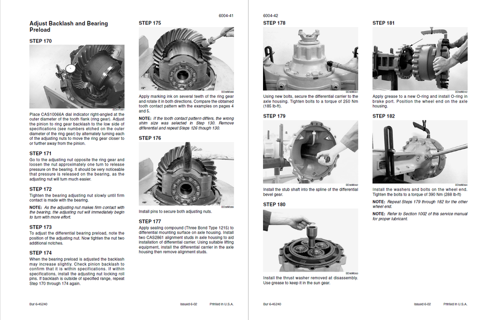
- ZF Axle Metrology & Multi-Disc Brake Limits: Eliminate the guesswork when servicing the driveline. The guide dictates exact wear limit measurements for the internal wet brakes, requiring a complete lined disc replacement if dimension "A" falls to 4.0 mm (0.16 inch). Furthermore, it details precise pinion distance adjustments based on convex (drive side) and concave (coast side) gear tooth contact patterns to prevent differential failure.
- Deep-Level CAN-Bus & TCU Error Decoding: Go far beyond basic code reading. The diagnostic section cracks open the ZF Transmission ECM and Information Center logic, providing step-by-step resolution paths for critical faults like Error 47000 (CAN interface failure) and Error 46243 (Internal TCU application error), guiding the technician to perform exact clutch calibrations directly from the cab.
Features & Highlights
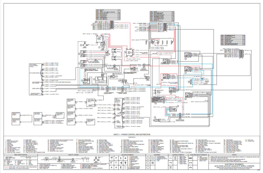
- Regional-Specific Fold-out Topography: The electrical section includes massive schematic posters with pin-to-pin wire tracing. It allows mechanics to track specific circuits, such as wire 36P (P-1.0-SXL) from connector 94M directly to the engine oil pressure switch. It even highlights regional circuit variations, such as configuring connectors 64M and 64F for North American versus European lighting standards.
- OEM Hydraulic Flow & Pressure Calibration: Equip your shop with factory testing protocols. The manual specifies the use of the CAS-1808 Flowmeter Kit and CAS-2702 Adapter to accurately measure the 174 to 178 L/min main pump output. It also provides the absolute pressure targets for dynamic tuning, such as setting the main relief valve strictly between 248 and 252 bar (3596 to 3654 psi).
- Information Center "Hack" & Override Protocols: Turn the operator's dashboard into a master diagnostic scanner. The text instructs technicians on how to bypass normal screens and access hidden engineering menus (such as Display Location 086 for digital input states or 171-190 for temporary fault codes), allowing for real-time monitoring of switch states and system health without external software.
Problem Solver
- Eradicating False Hydraulic Overheat Alarms: If the Information Center triggers a critical stop warning via Error 72110 (Hydraulic oil reaching 110°C/230°F), the troubleshooting tree prevents unnecessary cooler replacements. It guides the technician to test the hydraulic oil temperature sender for an internal short circuit measuring less than 50 ohms before dismantling the cooling package.
- Curing Phantom Brake Logic Faults: Stop chasing imaginary brake pressure losses. When the dashboard displays Error 61900 or 61901, the manual points directly to the 1700 PSI or 900 PSI redundant brake pressure switches. It details a specific 30-stroke service brake pedal procedure to reset the system logic and verify switch continuity.
- Pinpointing Implement Detent Failures: When the bucket return-to-dig or height control functions fail, the electrical matrix isolates the exact faulty component. It directs the mechanic to test connector 17M, requiring exactly 24 volts at specific pins to isolate a failed electromagnetic detent from a damaged proximity switch or a compromised ground circuit.
⚠️ Important Fitment & Coverage Note:As explicitly stated in the Section Index of this publication: "For Engine Repair, See the Engine Service Manual" and "For Fuel System Repair, See the Engine Service Manual." This manual thoroughly covers engine removal, installation, and complete hydraulic stall testing, but it does not include the internal teardown, machining, or honing of the diesel engine block.
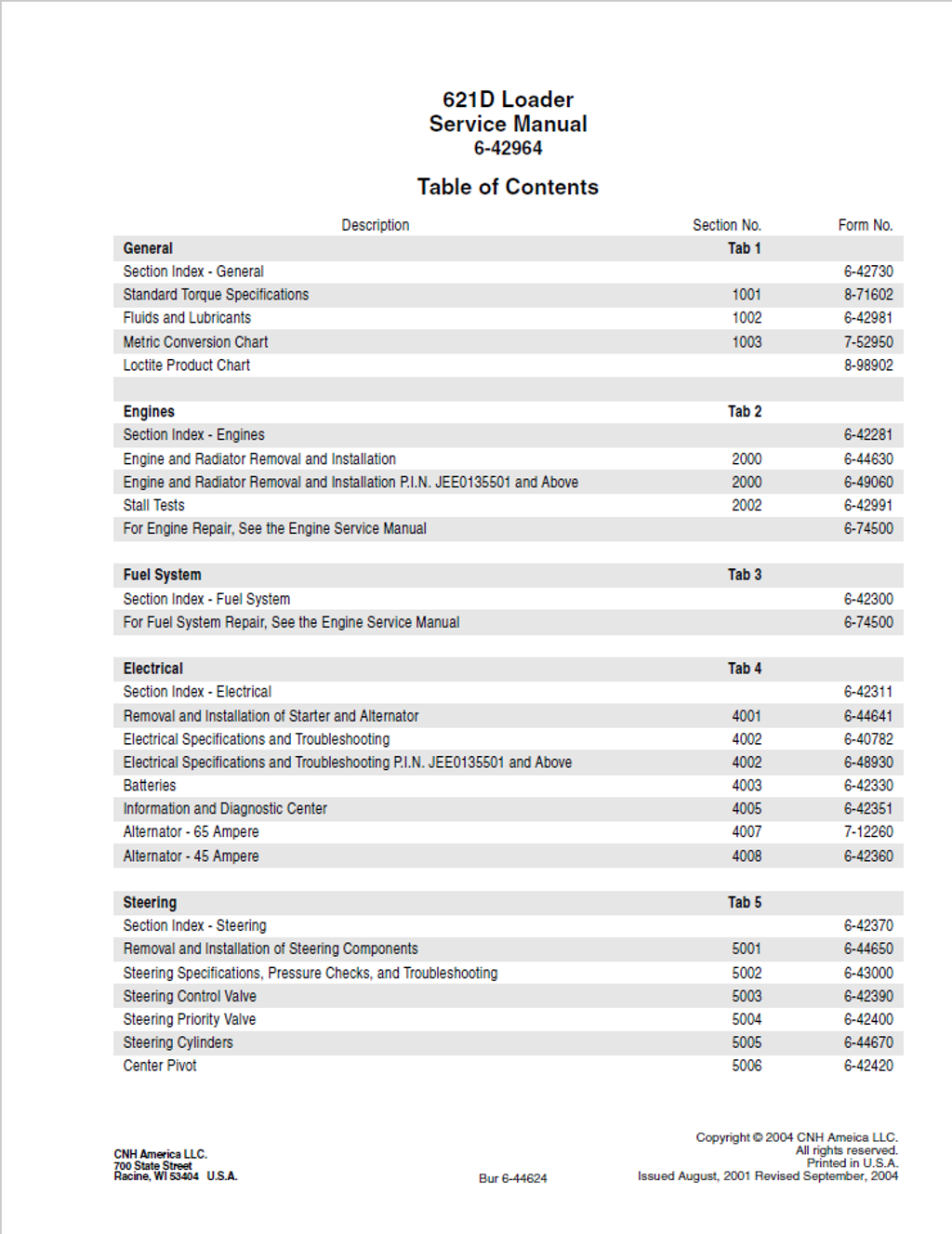
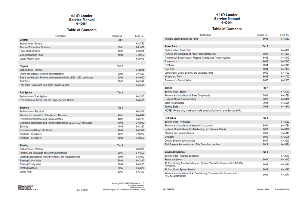
Table of Contents
- GENERAL
- Section Index - General
- Standard Torque Specifications
- Fluids and Lubricants
- CAPACITIES AND LUBRICANTS
- CONVERSION FORMULAS
- ENGINE OIL RECOMMENDATIONS
- DIESEL FUEL SYSTEM
- Fuel Storage
- Specifications for Acceptable No. 2 Diesel Fuel
- MAINTENANCE SCHEDULE
- Model 621D
- Metric Conversion Chart
- Loctite Product Chart
- ENGINES
- Section Index - Engines
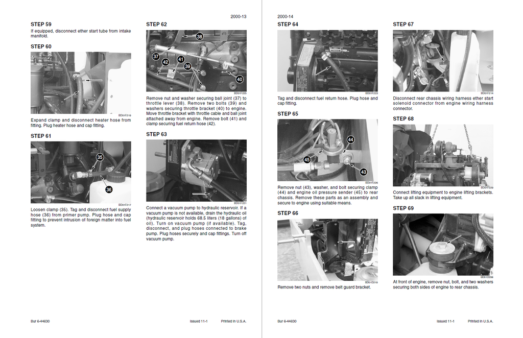
- Engine and Radiator Removal and Installation
- ENGINE
- Removal
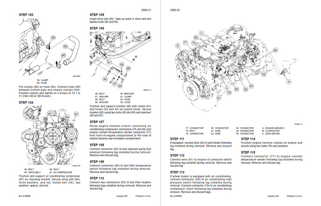
- Installation
- ENGINE
- Engine and Radiator Removal and Installation P.I.N. JEE0135501 and Above
- Stall Tests
- FUEL SYSTEM
- Section Index - Fuel System
- ELECTRICAL
- Section Index - Electrical
- Removal and Installation of Starter and Alternator
- Removal
- Installation
- STARTER
- P.I.N. JEE0135501 AND ABOVE
- Electrical Specifications and Troubleshooting
- SPECIFICATIONS
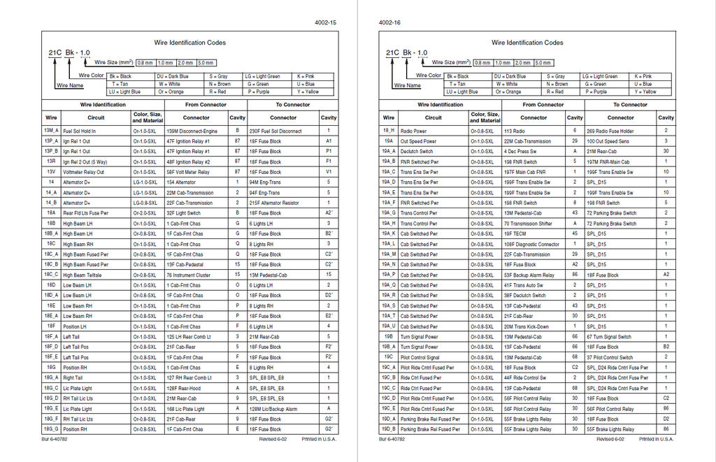
- ELECTRICAL WIRE IDENTIFICATION
- UNDERSTANDING THE TROUBLESHOOTING TABLES
- LOCATING COMPONENTS ON THE SCHEMATIC POSTERS
- TROUBLESHOOTING BATTERIES, FUEL SHUTOFF, CHARGING, STARTING, ALTERNATOR, ETHER START, IGNITION SWITCH AND RELAYS
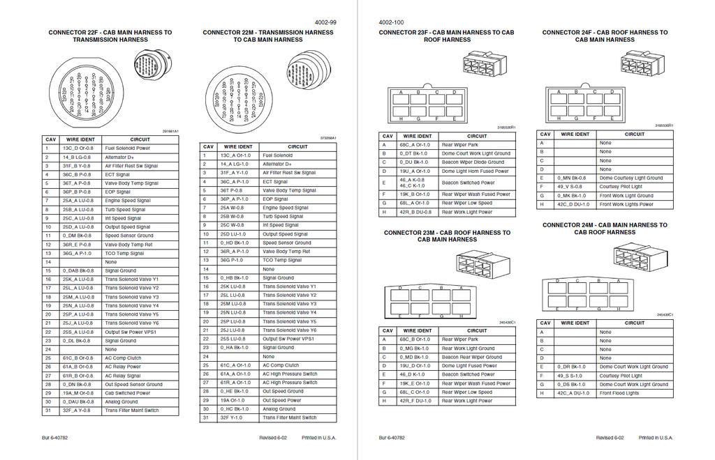
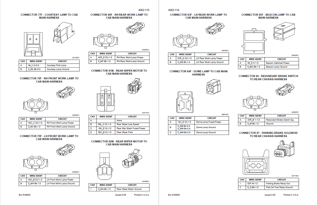
- CONNECTORS
- INDEX
- Electrical Specifications and Troubleshooting P.I.N. JEE0135501 and Above
- SPECIFICATIONS
- ELECTRICAL WIRE IDENTIFICATION
- UNDERSTANDING THE TROUBLESHOOTING TABLES
- LOCATING COMPONENTS ON THE SCHEMATIC POSTERS
- TROUBLESHOOTING BATTERIES, ENGINE FUEL SOLENOID, CHARGING, STARTING, ALTERNATOR, FUEL FILTER HEATER, GRID HEATER, IGNITION SWITCH AND RELAYS
- Batteries
- Master Disconnect Switch
- Engine Fuel Solenoid
- Alternator
- Starter Motor
- Starting Relay
- Fuel Filter Heater Relay No. 16
- Fuel Filter Heater Switch
- First Fuel Filter Heater
- Second Fuel Filter Heater (621D Only)
- Grid Heater Relay No. 15 (Option)
- Grid Heater (Option)
- Grid Heater Temperature Sensor (Option)
- Grid Heater Controller (Option)
- Neutral Start Relay No. 8
- Ignition Switch
- Ignition Relay No. 1
- CONNECTORS
- INDEX
- Batteries
- SAFETY RULES
- SPECIAL TOOLS
- MAINTENANCE
- Information and Diagnostic Center
- Service Indicator Icon
- WARNING DISPLAYS
- Critical Warning Displays
- Non-Critical Warning Displays
- INFORMATION AND DIAGNOSTIC CENTER
- Hourmeter
- Tachometer
- Speedometer
- Engine Coolant Temperature
- Engine Oil Pressure
- Fuel Level
- Transmission Oil Temperature
- Hydraulic Oil Temperature
- Voltmeter
- Transmission Display
- Alarm Check
- Coolant Level Check
- Brake Pressure
- Secondary Steering Pressure Switch
- Park Brake Information Center Output Check
- Pilot Lockout Information Output Check
- Hydraulic Filter Restriction Switch Check
- Air Filter Restriction Switch Check
- Work Lights Check
- Air Conditioning Switch Check
- Transmission Filter Restriction Switch Check
- Requested Gear Check
- Operational Indicator Status
- Actual Gear Check
- Drive Line Shift Status
- Hourmeter Indicator Status
- Tachometer Indicator Status
- Service Indicator Status
- Movement Indicator Status
- Beacon Status
- Redundant Brake Pressure Switch Check
- Service Brake Foot Switch Check
- Pilot Lockout Switch Check
- Display Location 047
- Minimum Gear Selection
- Maximum Gear Selection
- Gear Range Read Only
- Reset Diagnostic Stack for Locations 071 through 090
- Service Interval Hours
- Fault Code Status
- ZF Transmission ECM Part Number (1st part)
- DISPLAY LOCATION NUMBERS AND DESCRIPTIONS
- FAULT CODES
- INDEX
- Alternator - 65 Ampere
- SPECIFICATIONS
- SPECIAL TORQUES
- SPECIAL TOOLS
- GENERAL INSPECTION AND TESTING
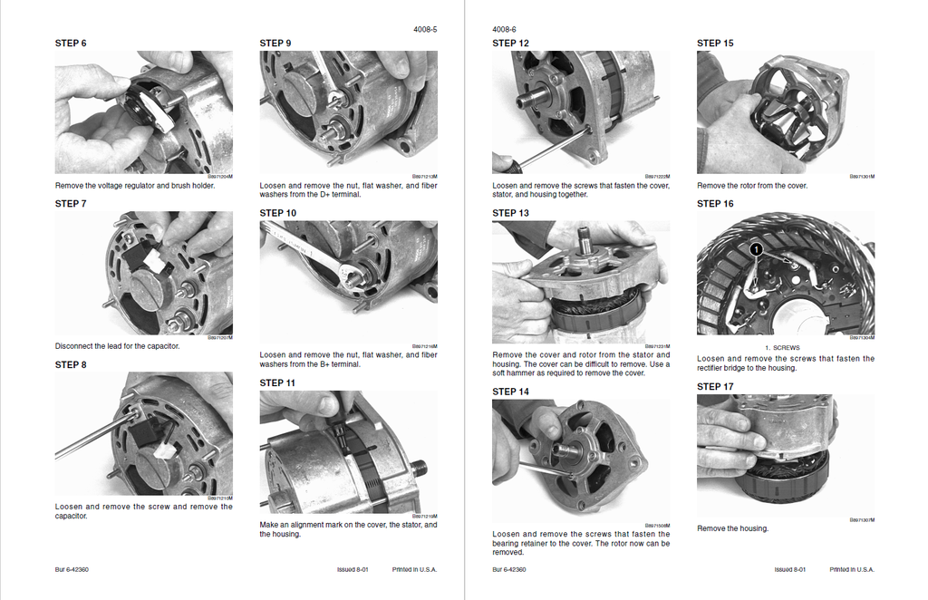
- ALTERNATOR DISASSEMBLY, TESTING, AND ASSEMBLY
- Disassembly and Testing
- Assembly
- Alternator - 45 Ampere
- STEERING
- Section Index - Steering
- Removal and Installation of Steering Components
- Steering Specifications, Pressure Checks, and Troubleshooting
- SPECIAL TOOLS
- TROUBLESHOOTING THE STEERING SYSTEM
- AUXILIARY STEERING SYSTEM PUMP TEST
- Steering Control Valve
- Disassembly
- Inspection
- Assembly
- Steering Priority Valve
- Disassembly
- Cleaning and Inspection
- Assembly
- SPECIAL TORQUES
- Steering Cylinders
- Disassembly
- Inspection
- Assembly
- Center Pivot
- SPECIFICATIONS
- SPECIAL TOOLS
- CENTER PIVOT
- Auxiliary Steering Motor and Pump
- POWER TRAIN
- Section Index - Power Train
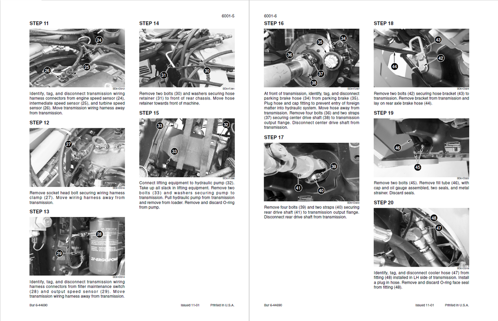
- Removal and Installation of Power Train Components
- SPECIAL TORQUES
- TRANSMISSION
- Transmission Specifications, Pressure Checks, and Troubleshooting
- Transmission
- SPECIAL TOOLS
- SPECIAL TORQUES
- SPECIFICATIONS
- DISASSEMBLY
- ASSEMBLY
- Front Axle
- DIFFERENTIAL CARRIER DISASSEMBLY
- DIFFERENTIAL DISASSEMBLY
- DRIVE PINION DISASSEMBLY
- BRAKE TUBES REMOVAL
- BRAKE TUBES INSTALLATION
- DIFFERENTIAL CARRIER ASSEMBLY
- Rear Axle
- Drive Shafts, Center Bearing, and Universal Joints
- SPECIAL TORQUES
- FRONT DRIVE SHAFT
- UNIVERSAL JOINTS
- Removal
- Installation
- Wheels and Tires
- WHEELS AND BOLTS
- General Information
- Torque Specification
- TIRE PRESSURE 621D
- CHANGING TIRES
- INSTALLING A WHEEL
- WHEELS AND BOLTS
- Transmission Control Valve
- SPECIAL TOOLS
- SPECIAL TORQUES
- DISASSEMBLY
- INSPECTION
- ASSEMBLY
- BRAKES
- Section Index - Brakes
- Removal and Installation of Brake Components
- Hydraulic Brake Troubleshooting
- Brake Accumulators
- SPECIAL TOOL
- DISCHARGING THE NITROGEN CHARGE ON AN ACCUMULATOR
- BRAKE ACCUMULATORS
- Disassembly
- Inspection
- Assembly
- Parking Brake
- HYDRAULICS
- Section Index - Hydraulics
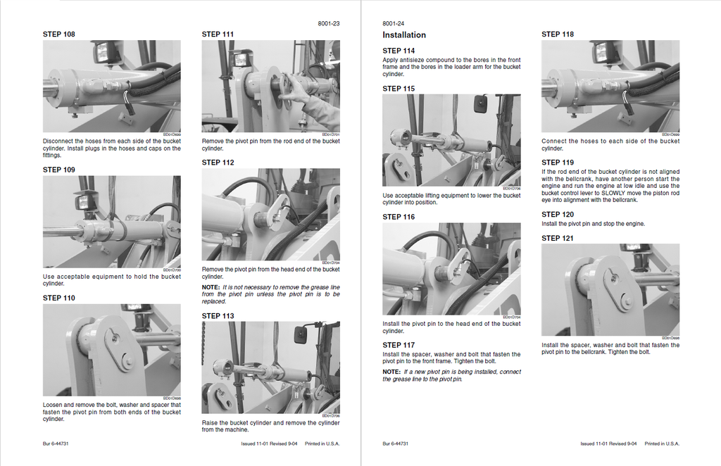
- Removal and Installation of Hydraulic Components
- Hydraulic Specifications, Troubleshooting, and Pressure Checks
- LIFT CYLINDERS
- Removal
- Installation
- TESTING THE RIDE CONTROL
- 621D HYDRAULIC COMPONENT LOCATIONS
- SPECIFICATIONS
- LIFT CYLINDERS
- Cleaning the Hydraulic System
- PORTABLE FILTER
- GENERAL INFORMATION
- TYPES OF CONTAMINATION
- CLEANING THE HYDRAULIC SYSTEM
- FLUSHING WATER FROM THE HYDRAULIC SYSTEM
- Cylinders
- Disassembly
- Inspection
- Assembly
- Coupler Solenoid Locking Valve
- Disassembly
- Inspection
- Assembly
- Pilot Pressure Accumulator and Ride Control Accumulator
- MOUNTED EQUIPMENT
- Section Index - Mounted Equipment
- Pedals and Levers
- Air Conditioning Troubleshooting and System Checks for Systems with HFC134a Refrigerant
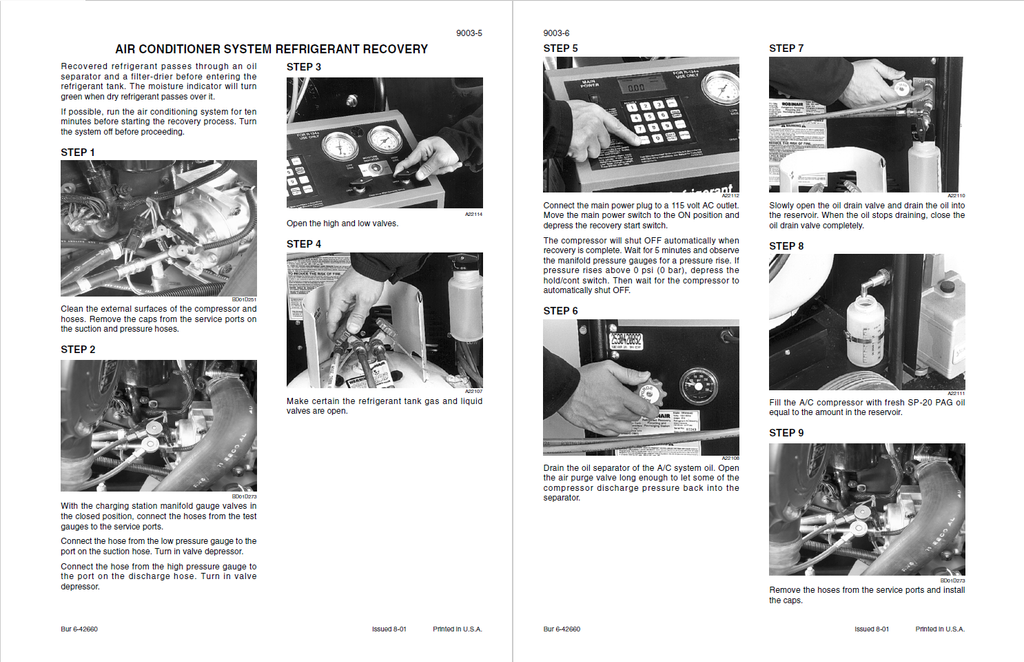
- Air Conditioning System Service
- Removal and Installation of Air Conditioning Components for Systems with HFC134a Refrigerant
- Loader
- ROPS Cab and ROPS Canopy
- SPECIAL TORQUES
- POSSIBLE DAMAGE TO THE ROPS CAB OR ROPS CANOPY
- MAINTENANCE AND INSPECTION OF THE ROPS CAB OR ROPS CANOPY
- ROPS CAB AND ROPS CANOPY
- Cab Glass Installation
- SCHEMATICS
- Electrical Schematic Foldouts and Hydraulic Schematic Foldout
- Electrical Schematic Foldouts and Hydraulic Schematic Foldout P.I.N. JEE0135501 and Above