

CASE Construction 721D Wheel Loader Service Manual 6-47281 English
Official Manual Overview
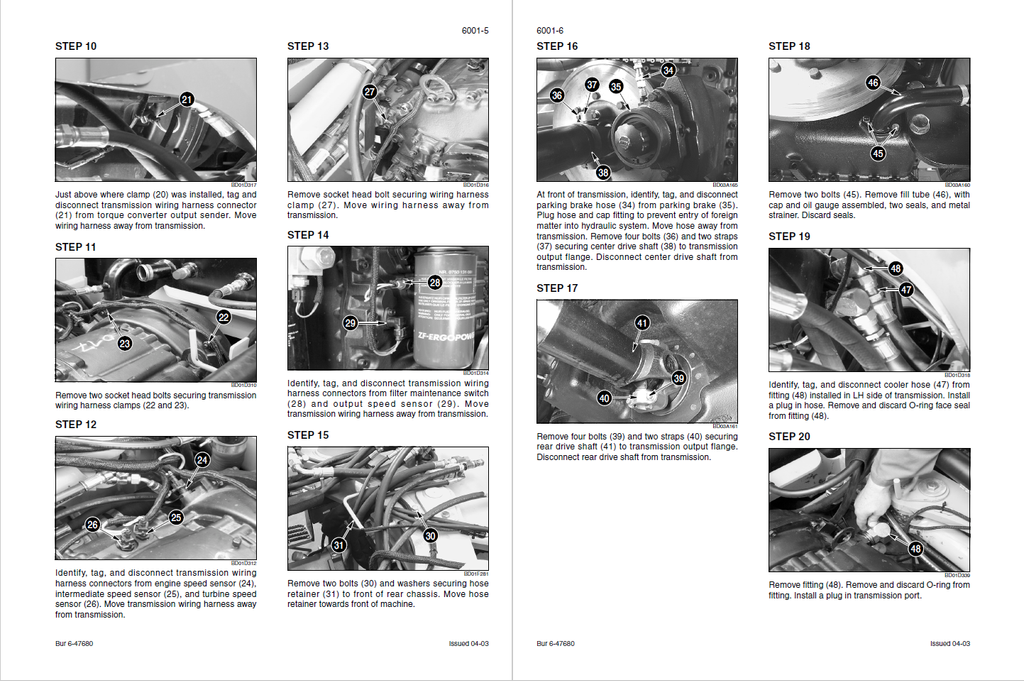
Step into the heavy-duty realm of the CASE 721D wheel loader with this comprehensive OEM Service Manual. Explicitly covering all linkage configurations—including standard Z-Bar, XR (Extended Reach), and XT (Tool Carrier) models—this master binder is engineered for elite technicians facing complex drivetrain and electro-hydraulic overhauls. It extensively documents advanced ZF transmission parameter calibrations (dictating optimal clutch fill times), heavy axle metrology (detailing exact pinion distance adjustments based on convex/concave gear tooth contact patterns), and provides a massive fold-out schematic breakdown of the EDC7 (Electronic Diesel Control) and CAN-Bus networks. Furthermore, it empowers mechanics to utilize the onboard Information and Diagnostic Center as a standalone scanner, unlocking hidden LCD menus (such as Display Locations 071-090) to retrieve temporary fault codes and monitor digital input states in real-time. Please note: while this guide fully maps out engine removal, radiator installation, and hydraulic stall tests, internal diesel engine machining and fuel system repairs are relegated to a separate dedicated engine manual.
- Brands: CASE Construction
- Equipment Type: Wheel Loader
- Manuals Type: Service Manual
- Machine Model: 721D (Z-Bar, XR, and XT models)
- Serial Number: All Serial Numbers
- Region: N/R
- Book Code: 6-47281
- Issued: Printed in France. May 2004
- Language: English
- Pages: 762
- File Format: PDF (Searchable)
Selling Points
- XT Cylinder & Heavy-Duty Linkage Overhaul: Avoid structural failure during high-breakout force operations. This manual dictates the absolute fastening limits for the 721D linkages, enforcing a massive 1780 to 2180 Nm (1312 to 1607 lb-ft) of torque specifically for the XT bucket cylinder piston bolt, alongside strict Loctite application standards.
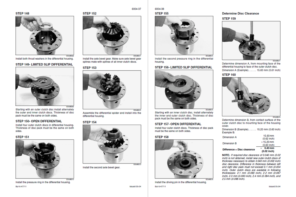
- Planetary Axle & Wet Brake Metrology: Execute clinical driveline restorations without the guesswork. The guide establishes strict dimensional wear limits for the heavy-duty axles, requiring total lined disc replacement if the multi-disc brake gap (Dimension "X") compresses to 4.0 mm (0.16 inch) or less. Furthermore, it mandates a crushing 700 to 1000 Nm of torque for the planetary carrier locknut.
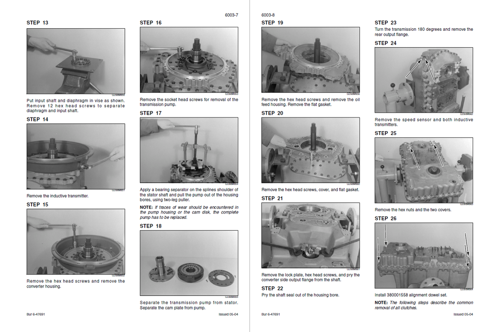
- Advanced Transmission ECM Parameter Management: Take total control over the ZF shifting logic. Utilizing the dedicated 380001577 valve adjustment toolset, this manual guides you through physical control valve teardowns while mapping out the electronic clutch filling parameters, resolving severe mechanical slip issues or calibration faults (such as Error 46245 and 46246).
Features & Highlights
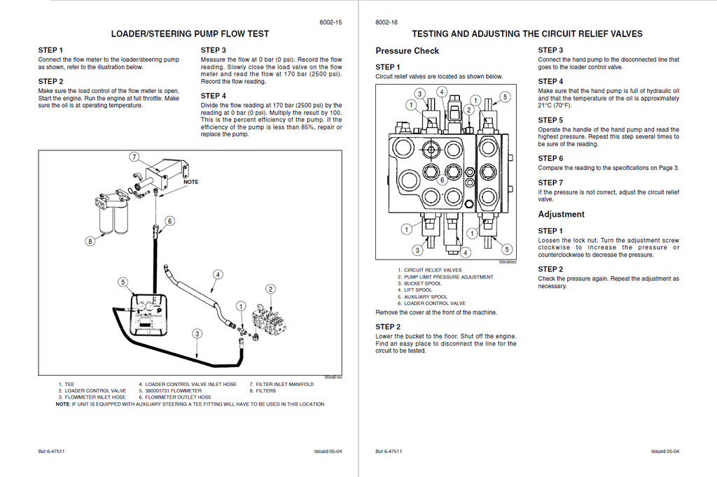
- Dynamic Hydraulic Benchmarking & Flow Testing: Equip your technicians with the exact factory flow parameters. Using the 380001740 Flowmeter kit, the manual provides the exact target data to validate pump health, demanding 117 to 125 L/Min at 138 bar from the steering pump, and establishing the main relief valve pressure strictly between 248 and 252 bar (3596 to 3654 psi).
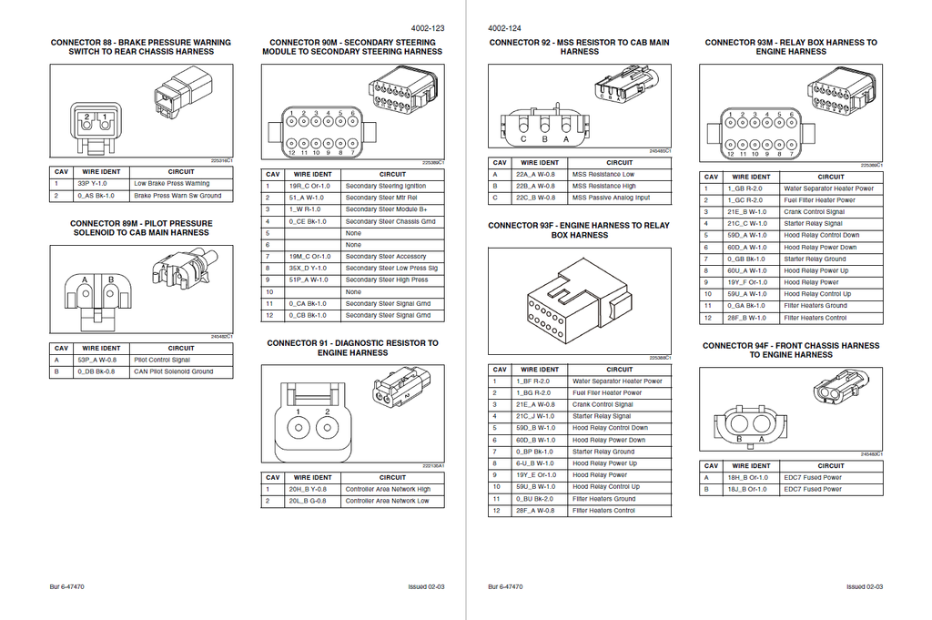
- Deep-Level CAN-Bus Topography & Resistance Matrices: Eliminate blind wire chasing across the articulated chassis. The electrical section maps out massive 70-pin connectors (like Connector 13F) to the exact cavity, identifying 50L_A (CAN Low) and 50H_A (CAN High) circuits. It also provides baseline ohmic values for sensors, dictating that a healthy hydraulic temperature sender must read exactly 133.9 ohms at 110°C.
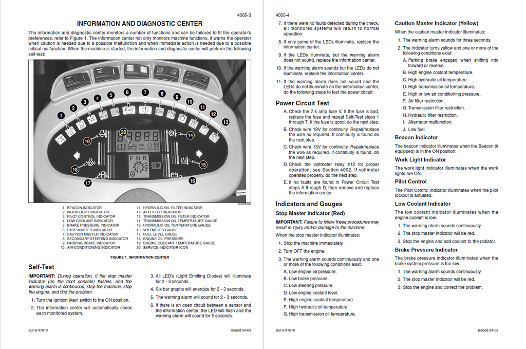
- On-Board LCD Telemetry & Memory Clearing: Transform the 721D's dashboard into a master diagnostic tool. The book reveals how to access locked engineering menus via the Program/Reset switch. Mechanics can navigate to Display Location 055 to perform a hard reset of the primary diagnostic stack (locations 071-090), or access locations 171-190 to monitor short-term, temporary fault codes in real-time.
Problem Solver
- Resolving Persistent Brake Code Anomalies: Stop replacing expensive control modules due to phantom brake alarms. If the cluster triggers Error 61901 (900 PSI Redundant brake pressure switch hasn't cycled), the troubleshooting tree directs the technician to physically pump the service brake 30 full strokes to force a system logic reset before investigating harness continuity.
- Defeating Communication & CAN Drops: When the entire driveline goes into safe mode due to an Error 47000 (CAN interface failure) or Error 47001 (Engine speed missing), the diagnostic charts isolate the exact Transmission Electronic Control Module (TECM) pathways. It guides you to verify the Vehicle Identification Number (VINS) synchronization and test the shielding of the twisted-pair data cables.
- Isolating False Hydraulic Overheats: If the machine enters a critical stop condition triggering Error 72110 (Hydraulic oil temperature at 110°C/230°F or greater), the manual prevents unnecessary oil cooler tear-downs. It instructs the mechanic to first interrogate the thermistor circuit, testing for an internal short that artificially spikes the gauge reading.
⚠️ Important Fitment & Coverage Note:As explicitly declared by the manufacturer in the Section Index, "For Engine Repair, See the Engine Service Manual" and "For Fuel System Repair, See the Engine Service Manual." This manual comprehensively covers the engine extraction, radiator installation, and combined hydraulic/torque converter stall tests, but it does not contain the internal machining, honing, or teardown procedures for the diesel engine block.
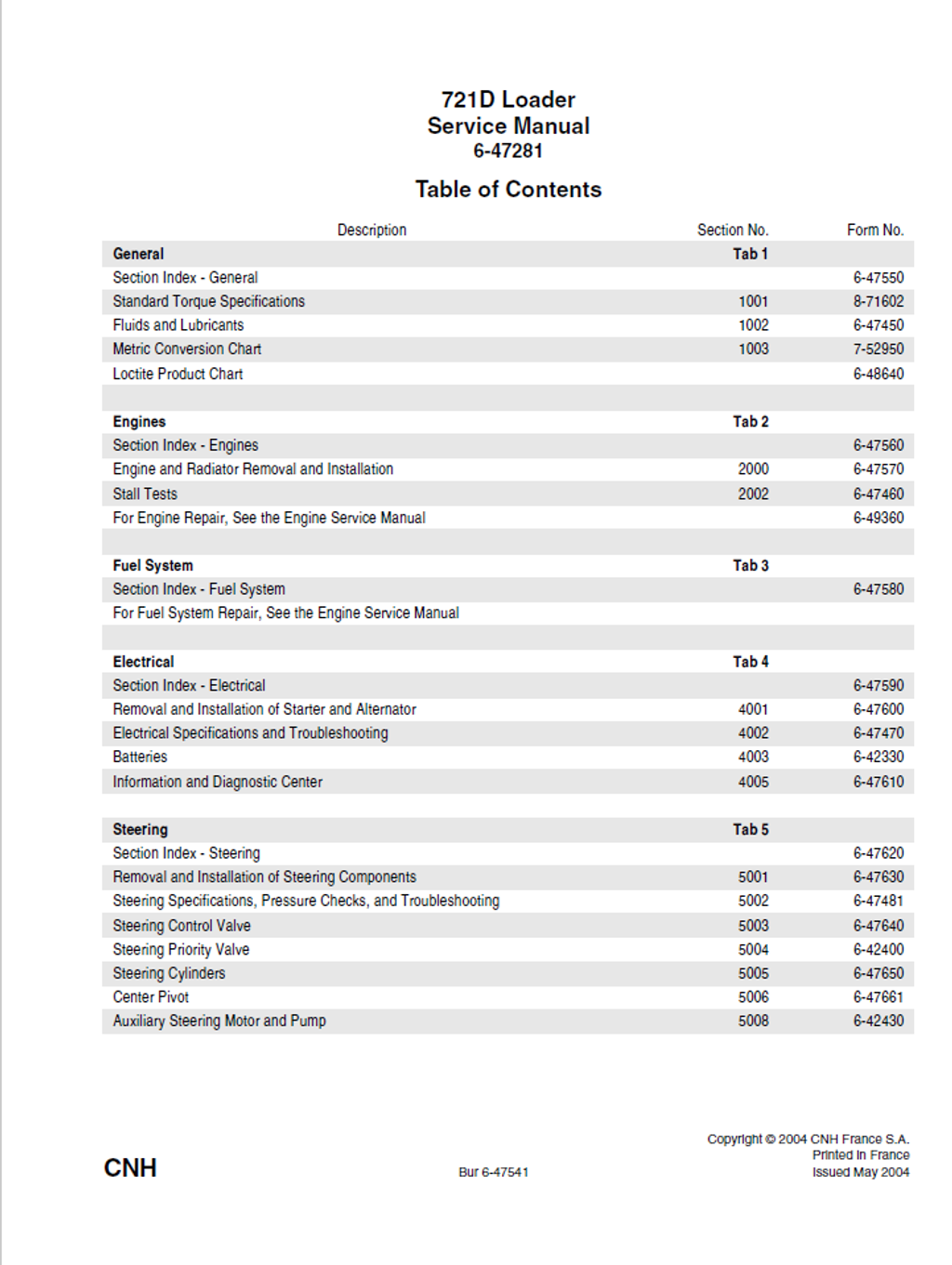
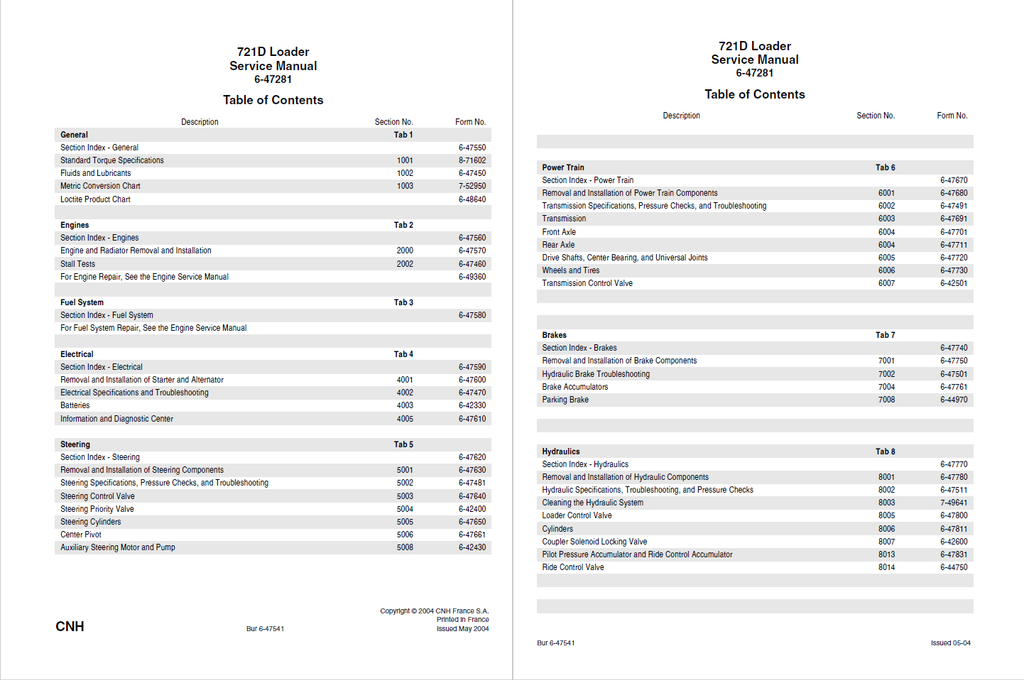
Table of Contents
- GENERAL
- Section Index - General
- Standard Torque Specifications
- Fluids and Lubricants
- Capacities and Lubricants
- Engine Oil Recommendations
- Diesel Fuel System
- Fuel Storage
- Specifications for Acceptable No. 2 Diesel Fuel
- Maintenance Schedule
- Model 721D
- Metric Conversion Chart
- Loctite Product Chart
- ENGINES
- Section Index - Engines
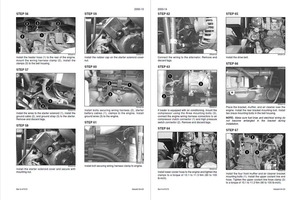
- Engine and Radiator Removal and Installation
- Stall Tests
- FUEL SYSTEM
- Section Index - Fuel System
- ELECTRICAL
- Section Index - Electrical
- Removal and Installation of Starter and Alternator
- Starter
- Removal
- Installation
- Alternator
- Starter
- Electrical Specifications and Troubleshooting
- Specifications
- Electrical Wire Identification
- Wire Identification Codes
- Wire Identification From Connector To Connector
- Understanding the Troubleshooting Tables
- Locating Components On The Schematic Posters
- Troubleshooting Batteries, Electronic Diesel Control, Charging, Starting, Alternator, Heaters, Throttle Pedal, Ignition Switch and Relays
- Batteries
- Master Disconnect Switch
- Electronic Diesel Control (EDC 7)
- Alternator
- Starter Motor
- Starting Relay
- Crank Control Relay
- Water Separator Heater
- First Fuel Filter Heater
- Grid Heater Relay
- Grid Heater
- Throttle Potentiometer
- Engine Control Relay No. 6
- Neutral Start Relay No. 8
- Ignition Switch
- Ignition Relay No. 1
- Ignition Relay, Accessory Relay, Voltmeter Relay, and Time Delay Module
- Ignition Relay No. 2
- Accessory Relay No. 3
- Voltmeter Relay No. 12
- Time Delay Module
- Diagnostic Switch
- MSS Relay No. 16
- Relay Socket No. 11
- Transmission Solenoids, Sensors and Switches, Control Module, Shifter, Diagnostic Connector, and Back-up Alarm
- Output Speed Sensor
- Engine Speed Sensor
- Intermediate Speed Sensor
- Turbine Speed Sensor
- Filter Maintenance Switch
- Torque Converter Output Temperature Sender
- Transmission Solenoid Valve and Temperature Sensors
- Transmission Electronic Control Module
- Transmission Shifter
- Diagnostic Connector
- Transmission Kick-down Switch
- Transmission Auto Switch
- Declutch Switch
- Brake Declutch Pressure Switch
- Transmission Enable Switch
- FNR Switch
- Back-up Alarm Relay No. 7
- Back-up Alarm Disable Switch
- Back-up Alarm
- Indicator Switches and Senders, Program/Reset Switch, Park Brake Switch, Instrument Cluster, Pilot Control Switch, and Up/Down Count Switch
- Brake Warning Pressure Switch
- Coolant Level Sender
- Fuel Level Sender
- Hydraulic Oil Temperature Sender
- Hydraulic Filter Restriction Switch
- Engine Coolant Temperature Sender
- Air Filter Restriction Switch
- Program/Reset Switch
- Parking Brake Switch
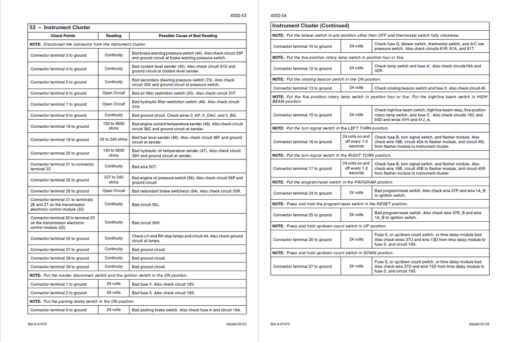
- Instrument Cluster
- Pilot Control Switch
- Up/down Count Switch
- Engine Oil Pressure Switch, Pilot Control, Parking Brake, Water Separator Sensor, and Redundant Brake Switches
- Engine Oil Pressure Switch
- Pilot Control Relay No. 10
- Parking Brake Relay No. 9
- Parking Brake Solenoid
- Pilot Pressure Solenoid
- Water Separator Sensor
- Fan Reversing Switch (Option)
- Fan Reversing Solenoid (Option)
- Redundant Brake Pressure Switches
- Bucket Controls
- Detent Switch
- Bucket Control Valve Electromagnetic Detents
- Return-To-Travel/Float Switch
- Return-To-Dig Proximity Switch
- Height Control/Return-To-Travel Proximity Switch
- Rollback Pressure Switch (Option)
- Float Solenoid
- Secondary Steering Components and Ride Control
- Secondary Steering Module (Option)
- Secondary Steering Pressure Switch (Option)
- Secondary Steering Motor (Option)
- Secondary Steering Solenoid (Option)
- Pin Engage Switch (Option)
- Pin Engage Solenoid (Option)
- Ride Control Switch
- Ride Control Relay No. 4
- Ride Control Solenoid
- External Lights and Signals, Rotary Lamp Switch, and Cab Lights
- Left Hand Rear Combination Lamp
- Right Hand Rear Combination Lamp
- Left Hand Front Combination Lamp
- Right Hand Front Combination Lamp
- Left Hand Rear Work Lamp
- Right Hand Rear Work Lamp
- Left Hand Front Work Lamp
- Right Hand Front Work Lamp
- Five Position Rotary Lamp Switch
- High/Low Beam Relay No. 13
- License Plate Lamp
- Dome Lamp
- Courtesy Lamp
- Connectors
- Index
- Batteries
- Information and Diagnostic Center
- Warning Displays
- Critical Warning Displays
- Non-Critical Warning Displays
- Information and Diagnostic Center
- Hourmeter
- Tachometer
- Speedometer
- Engine Coolant Temperature
- Engine Oil Pressure
- Fuel Level
- Transmission Oil Temperature
- Hydraulic Oil Temperature
- Voltmeter
- Transmission Display
- Settings, Diagnostics, and Fault Codes
- Programming the Information Center
- Display Location Numbers and Descriptions
- Fault Codes
- Engine Fault Codes
- Accessing Fault Codes
- Erasing Fault Codes
- Engine Fault Code Failure Chart
- Index
- Warning Displays
- STEERING
- Section Index - Steering
- Removal and Installation of Steering Components
- Auxiliary Steering Pump and Motor
- Removal
- Installation
- Steering Cylinder
- Removal
- Installation
- Auxiliary Steering Pump and Motor
- Steering Specifications, Pressure Checks, and Troubleshooting
- Special Tools
- Troubleshooting the Steering System
- Auxiliary Steering System Pump Test
- Steering Cylinder Leak Test
- Steering Control Valve
- Disassembly
- Inspection
- Assembly
- Steering Priority Valve
- Disassembly
- Inspection
- Assembly
- Steering Cylinders
- Center Pivot
- Disassembly
- Assembly
- Connecting the Front Frame to the Rear Frame
- Auxiliary Steering Motor and Pump
- Specifications
- Auxiliary Steering Motor and Pump
- Disassembly
- Inspection
- Assembly
- POWER TRAIN
- Section Index - Power Train
- Removal and Installation of Power Train Components
- Transmission
- Removal
- Transmission Mounting
- Installation
- Transmission
- Transmission Specifications, Pressure Checks, and Troubleshooting
- Special Tools
- Specifications
- Transmission Operation
- Transmission Pressure Test Points Diagram
- Chart for Recording Pressure Readings
- Pressure Test Results
- All or Most Pressures Low and/or Flow Test Low
- Some Pressures Low
- Not Enough Power
- Machine Stops or Hesitates While Shifting - Intermittent
- Transmission
- Front Axle
- Special Tools
- Gear Tooth Contact Patterns
- Lubrication
- Wear Measurement on Multi-Disc Brake
- Wheel End and Brakes
- Disassembly
- Cleaning and Inspection
- Assembly
- Brake Hydraulics Leakage Test
- High Pressure Test
- Low Pressure Test
- Differential Carrier Disassembly
- Differential Disassembly
- Drive Pinion Disassembly
- Brake Tubes Removal
- Brake Tubes Installation
- Differential Carrier Assembly
- Rear Axle
- Drive Shafts, Center Bearing, and Universal Joints
- Special Torques
- Front Drive Shaft
- Wheels and Tires
- Transmission Control Valve
- BRAKES
- Section Index - Brakes
- Removal and Installation of Brake Components
- Hydraulic Brake Troubleshooting
- Specifications
- Special Tool
- Troubleshooting the Hydraulic Brake System
- Checking the Nitrogen Charge in the Accumulator
- Charging the Accumulator with Dry Nitrogen
- Bleeding the Brake System
- Brake Modulation Pressure Check
- Brake Accumulators
- Parking Brake
- HYDRAULICS
- Section Index - Hydraulics
- Removal and Installation of Hydraulic Components
- Removal and Installation of the Hydraulic Pump
- Removal
- Installation
- Removal and Installation of the Lift Cylinders
- Removal
- Installation
- Removal and Installation of the Bucket Cylinder - Z-Bar Loader
- Removal
- Installation
- Removal and Installation of the Bucket Cylinders - XT Loader
- Removal
- XT Loader Bucket Cylinder Removal And Installation Illustration
- Installation
- Removal and Installation of the Oil Cooler
- Removal
- Installation
- Removal and Installation of the Fan Reversing Valve
- Removal
- Installation
- Removal and Installation of the Hydraulic Pump
- Hydraulic Specifications, Troubleshooting, and Pressure Checks
- Specifications
- Special Tools
- Troubleshooting Procedure
- Problems in All Circuits
- Problem in All Loader Circuits
- Problem in the Braking Circuit
- Problem in a Single Loader Circuit
- Problem in the Steering Circuit
- Problem in the Ride Control
- Testing and Adjusting the Loader/Steering Pump Differential Pressure
- Pressure Check
- Adjusting the Loader/Steering Pump Differential Pressure
- Testing and Adjusting the Loader/Unloading Pump Differential Pressure
- Pressure Check
- Adjusting the Loader/Unloading Pump Differential Pressure
- Testing and Adjusting the Loader Limit Pressure
- Pressure Check
- Adjusting the Loader Limit Pressure
- Testing and Adjusting the Steering Limit Pressure
- Pressure Check
- Adjusting the Steering Limit Pressure
- Testing and Adjusting the Loader Pump Cutoff Pressure
- Pressure Check
- Adjusting the Loader Pump Cutoff Pressure
- Testing the Hydaulic Controller Pilot Supply Pressure
- Pressure Check
- Loader/Steering Pump Flow Test
- Testing and Adjusting the Circuit Relief Valves
- Pressure Check
- Adjustment
- Testing the Ride Control
- 721D Hydraulic Component Locations
- Cleaning the Hydraulic System
- Special Tools
- General Information
- Types of Contamination
- Cleaning the Hydraulic System
- Flushing Water from the Hydraulic System
- Loader Control Valve
- Disassembly
- Inspection
- Assembly
- Cylinders
- Bucket Cylinders for XT Models
- Disassembly
- Inspection
- Assembly
- Bucket Cylinders for XT Models
- Coupler Solenoid Locking Valve
- Disassembly
- Inspection
- Assembly
- Pilot Pressure Accumulator and Ride Control Accumulator
- Ride Control Valve
- Insert Valve
- Logic Cover
- Directional Valve
- Pressure Relief Valve
- MOUNTED EQUIPMENT
- Section Index - Mounted Equipment
- Air Conditioning Troubleshooting and System Checks For Systems with HFC-134a Refrigerant
- Air Conditioner System Service
- Removal and Installation of Air Conditioning Components For Systems with HFC-134a Refrigerant
- Loader
- Specifications
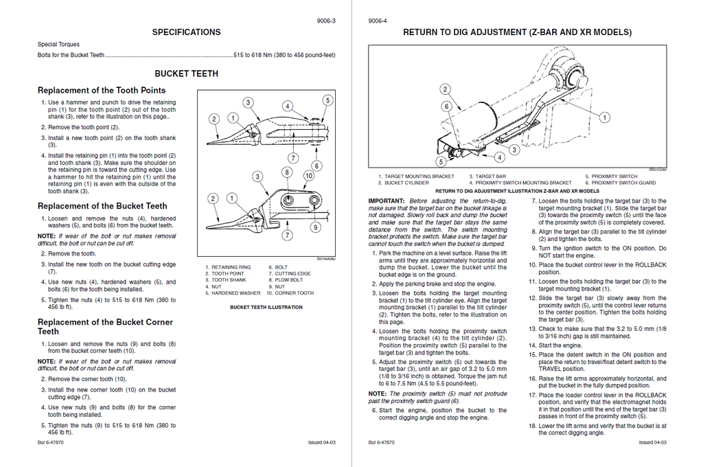
- Bucket Teeth
- Replacement of the Tooth Points
- Replacement of the Bucket Teeth
- Replacement of the Bucket Corner Teeth
- Return to Dig Adjustment (Z-Bar and XR Models)
- Height Control and Return to Travel Adjustment (Z-Bar, XR and XT Models)
- Return to Dig Adjustment (XT Models)
- Removing the Loader Frame (Z-Bar and XR Models)
- Installing the Loader Frame (Z-Bar and XR Models)
- Removing the Loader Frame (XT Models)
- Installing the Loader Frame (XT Models)
- ROPS Cab and ROPS Canopy
- Cab Glass Installation
- SCHEMATICS
- Electrical Schematic Foldouts and Hydraulic Schematic Foldout