

CASE Construction 821C Wheel Loader Service Manual 7-12102 English
Official Manual Overview
Maximize the uptime of your heavy-duty fleet with this definitive OEM Service Manual specifically compiled for the CASE 821C Wheel Loader. Engineered for elite technicians, this master binder bypasses basic maintenance to focus on deep-level diagnostic and overhaul protocols. It heavily emphasizes the advanced Transmission Electronic Control Module (ECM) and the onboard Information and Diagnostic Center, providing exhaustive wiring schematics and step-by-step logic trees for tracing CAN faults and resolving critical dash alarms. Beyond electrical topography, it delivers uncompromising hydraulic metrology, requiring the use of factory CAS-10280 Flowmeters and CAS-1804/CAS-1904 Pressure Test Kits to dynamically benchmark the priority valves, steering cylinders, and the 3-spool loader control valves. Please note: In strict accordance with the manufacturer's publication structure, while this guide extensively covers engine/radiator removal and hydraulic stall tests, internal diesel engine machining and fuel system repairs are relegated to a separate, dedicated engine manual.
- Brands: CASE Construction
- Equipment Type: Wheel Loader
- Manuals Type: Service Manual
- Machine Model: 821C
- Serial Number: All Serial Numbers
- Region: N/R
- Book Code: 7-12102
- Issued: Printed in U.S.A. May, 1999
- Language: English
- Pages: 716
- File Format: PDF (Searchable)
Selling Points
- Heavy-Duty Axle & Differential Metrology: Rebuild the driveline with absolute structural integrity. This manual provides exhaustive disassembly procedures for the 407, 409, and heavy-duty 411 planetary axles. It demands precise gear meshing, specifying a strict ring and pinion backlash of 0.3 to 0.4 mm, and enforces a massive fastening torque of 1500 Nm (1106 lb-ft) for the 411 axle planetary carrier retaining nut using the CAS-2284 socket.
- ZF Transmission ECM & Clutch Parametrics: Eliminate shifting hesitation and clutch slippage without the guesswork. The guide deeply analyzes the ZF transmission architecture, establishing baseline main pressure requirements of 16 to 18 bar (230 to 265 psi). It details exactly how to execute a clutch calibration procedure (AEB) via the in-cab Information Center, resolving critical slippage faults such as Error 46177 (Clutch K1) and Error 46182 (Clutch KR).
- Denison Hydraulic System Calibration: Equip your bay with factory-level flow testing doctrines. Specifying the use of the CAS-10280 Flowmeter and CAS-1804 Pressure Test Kit, this volume guides technicians to dynamically benchmark the primary and secondary pumps. It dictates absolute target parameters, requiring the unloader valve pressure to be dialed in perfectly between 145 to 158 bar (2100 to 2300 psi) to maintain maximum bucket breakout force.
Features & Highlights
- Information Center "Hacking" & Digital Calibration: Take master control over the loader's onboard computer. The manual reveals the hidden access codes (Display Locations 000-199) to enter the restricted Test Mode. Technicians can manually navigate to Location 042 to perform a Master Reset, or access Location 130 to recalibrate the speedometer and tire size logic (clearing corrupt data Error 86020).
- Micro-Tolerance Starter & Alternator Overhauls: Stop throwing away rebuildable electrical components. The electrical section provides clinical teardown specifications for the starting motor, strictly requiring the armature shaft runout to remain under 0.05 mm (0.002 inch) and the commutator mica to be undercut precisely to a depth of 0.8 mm to 1.0 mm (0.03 to 0.04 inch) to prevent brush arcing.
- Wet Brake Disc Dimensional Standards: Ensure maximum stopping power and safety compliance. During axle overhauls, the manual outlines the exact Brake Disc Clearance Procedure, mandating that the total clearance for a 3-friction-disc configuration must be shimmed strictly between 2.4 to 2.8 mm, preventing premature wear or hydraulic piston over-extension.
Problem Solver
- Defeating ZF Limp-Home & CAN-Bus Drops: When the entire driveline locks into 3rd gear safe mode, the diagnostic matrix isolates the communication breakdown. If the cluster triggers Error 47000 (CAN interface failure) or Error 47001 (Engine speed missing), it walks the technician through interrogating the twisted-pair data cables between the cluster controller and the Transmission Electronic Control Module (TECM) before replacing expensive computer modules.
- Isolating False Hydraulic Temp Alarms: Stop chasing imaginary fluid overheating issues. If the red STOP master indicator flashes and the buzzer sounds for a critical hydraulic temperature fault, the electrical topography directs you to probe the 36H circuit. It establishes that a healthy temperature sender must return approximately 5 volts at terminal A; anything less indicates a dead sensor or a shorted harness, preventing an unnecessary oil cooler teardown.
- Resolving "Crank-No Start" Interlock Failures: When the starter motor refuses to engage, the troubleshooting tree systematically bypasses the parts cannon. It guides mechanics to test the Neutral Start Relay #8 and the Fuel Shutoff Solenoid, verifying the exact presence of 24 volts on the 21K wire to definitively isolate a damaged ignition switch from a failed transmission declutch sensor.
⚠️ Important Fitment & Coverage Note:As explicitly mandated by the manufacturer in the primary index: "For Engine Repair, See the Engine Service Manual" and "For Fuel System Repair, See the Engine Service Manual." This master binder comprehensively details the engine/radiator extraction, combined hydraulic/torque converter stall tests, and all chassis-level systems, but it absolutely does not contain the internal machining, honing, or fuel injection pump rebuild procedures for the diesel engine block.
Table of Contents
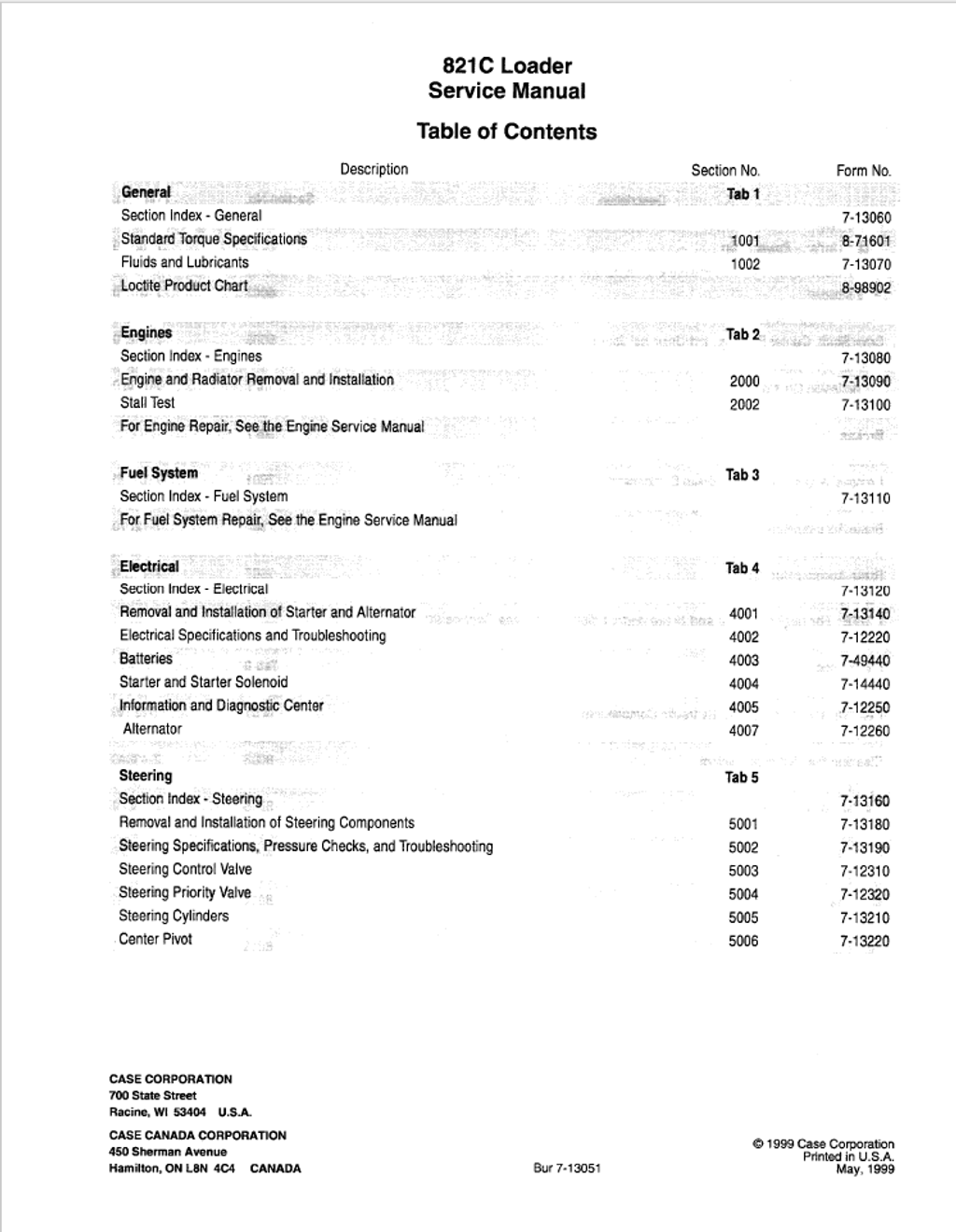
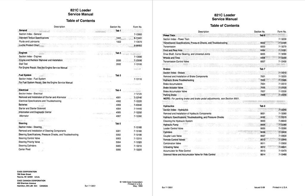
- GENERAL
- Fluids and Lubricants
- Diesel Fuel System
- Fuel Storage
- Specifications for Acceptable No. 2 Diesel Fuel
- Diesel Fuel System
- Maintenance Schedule Model 821C
- Loctite Product Chart
- Fluids and Lubricants
- ENGINES
- Section Index - Engine
- Engine and Radiator Removal and Installation
- Specifications
- Special Tools
- Engine
- Removal
- Installation
- Radiator
- Removal
- Installation
- Stall Tests
- Specifications
- Stall Tests
- Procedure to Heat the Oil
- Torque Converter
- Hydraulic System
- Test No. 1 - Torque Converter and Hydraulic Stall Together
- Understanding the Results of Test No. 1
- Test No. 2 - Torque Converter Stall
- Understanding the Results of Test No. 2
- Test No. 3 - Hydraulic Stall
- Understanding Results of Test No. 3
- FUEL SYSTEM
- Section Index - Fuel System
- ELECTRICAL
- Section Index - Electrical
- Removal and Installation of Starter and Alternator
- Information and Diagnostic Center
- Alternator
- Electrical Specifications, Troubleshooting, and Schematics
- Circuit Diagram Legend, Color Abbreviations, and Notes
- How to Use This Section
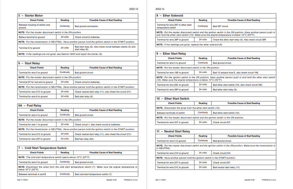
- Troubleshooting Batteries, Fuel Shutoff, Charging, Starting, Alternator, Cold Start, Ignition Switch and Relays
- Batteries
- Master Disconnect Switch
- Fuel Shutoff Solenoid
- Alternator
- Starter Motor
- Start Relay
- Fuel Relay
- Cold Start Temperature Switch
- Ether Solenoid
- Ether Start Relay
- Ether Start Switch
- Neutral Start Relay
- Ignition Switch
- Ignition Relay #1
- Troubleshooting Transmission Solenoids, Sensors and Switches, Control Module, Shifter, Diagnostic Connector, and Back-up Alarm
- Output Speed Sensor
- Engine Speed Sensor
- Intermediate Speed Sensor
- Turbine Speed Sensor
- Filter Maintenance Switch
- Torque Converter Output Temperature Sender
- Transmission Solenoid Valve and Temperature Sensors
- Transmission Electronic Control Module
- Transmission Shifter
- Diagnostic Connector
- Transmission Kick-down Switch (Located In Hydraulic Controller)
- Transmission Auto Switch
- Declutch Switch
- Declutch Brake Switch
- Back-up Alarm Relay #7
- Back-up Alarm Disable Switch
- Back-up Alarm
- Troubleshooting Indicator Switches and Senders, Program Reset Switch, Park Brake Switch, Instrument Cluster, Pilot Control Switch, and Up/Down Count Switch
- Brake Warning Pressure Switch
- Coolant Level Sender
- Fuel Level Sender
- Hydraulic Oil Temperature Sender
- Hydraulic Filter Restriction Switch
- Engine Coolant Temperature Sender
- Air Filter Restriction Switch
- Program Reset Switch
- Park Brake Switch
- Instrument Cluster
- Pilot Control Switch
- Up/down Count Switch
- Troubleshooting Engine Oil Pressure Sender, Pilot Control, Parking Brake, Engine Automatic Shutdown Relay, and Redundant Brake Switches
- Engine Oil Pressure Sender
- Pilot Control Relay
- Parking Brake Relay
- Redundant Parking Brake Solenoids
- Pilot Pressure Solenoid
- Redundant Brake Switches
- Engine Automatic Shutdown Relay Socket #11
- Troubleshooting Bucket Controls
- Detent Switch
- Bucket Control Valves Detent Electromagnets
- Return-To-Travel/Float Switch
- Return-To-Dig Proximity Switch
- Height Control Proximity Switch
- Return-To-Travel Proximity Switch
- Troubleshooting Secondary Steering Components and Ride Control
- Secondary Steering Relay with Lockout
- Secondary Steering Switch
- Secondary Steering Pump/Motor
- Pin Engagement Switch
- Pin Engage Solenoid
- Ride Control Switch
- Hoist-up Pressure Switch
- Ride Control Relay
- Bucket Dump Pressure Switch
- Bucket Rollback Pressure Switch
- Ride Engage Solenoid
- Troubleshooting Wiper/Washer
- Front Wiper Motor
- Front Rotary Wiper and Washer Switch
- Front Washer Pump Motor
- Rear Washer Pump Motor
- Rear Wiper and Washer Switch
- Rear Wiper Motor
- Compressor Clutch
- Condenser Fan Relay
- Condenser Fan Motor No. 1
- Condenser Fan Motor No. 2
- Engine Compartment Lamp (European Models)
- Engine Compartment Lamp Switch (European Models)
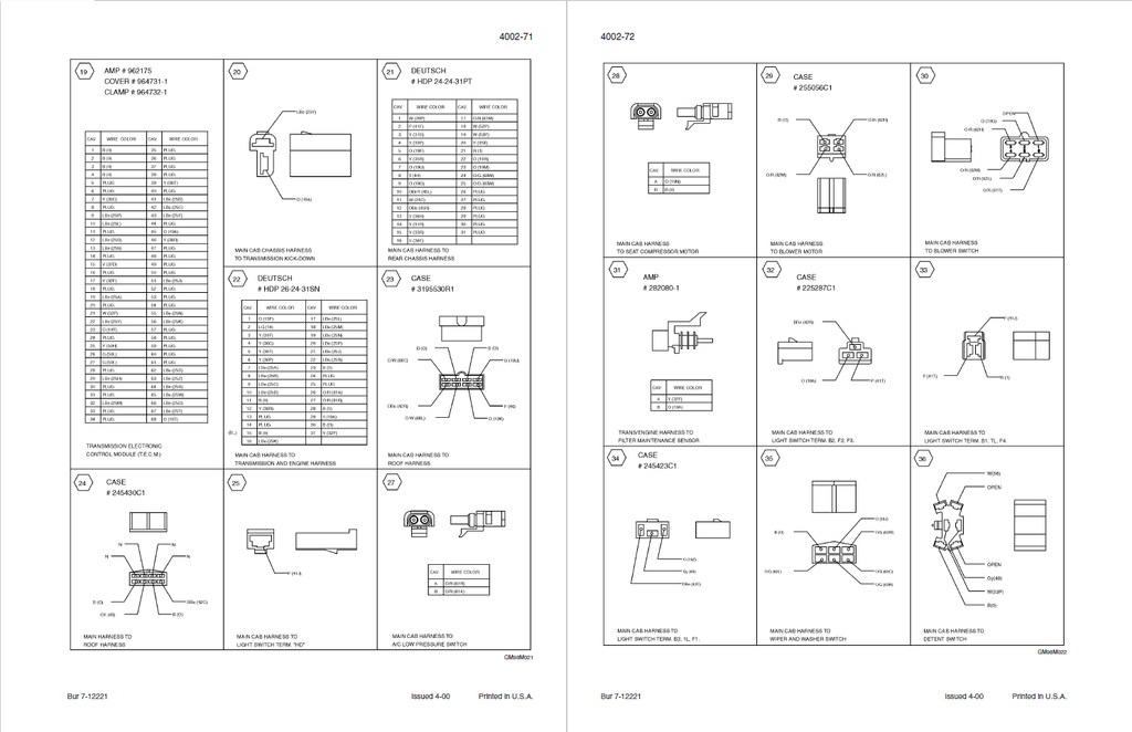
- Connectors
- Electrical Schematic - Sheets 29, 30, 31, and 32
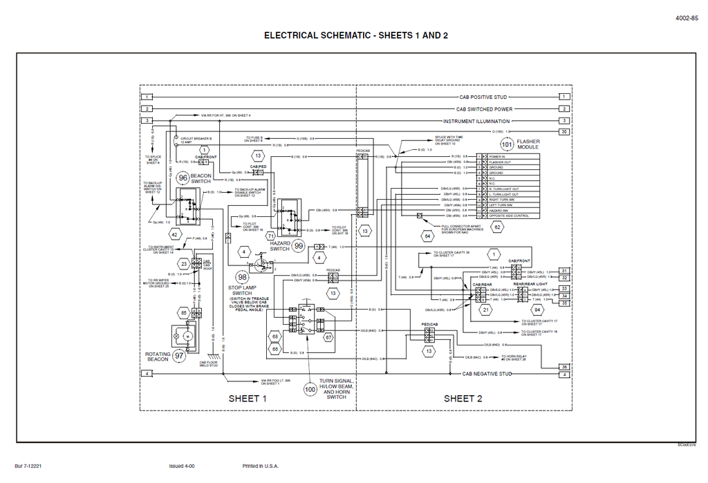
- Electrical Schematic - Sheets 1 and 2
- Electrical Schematic - Sheet 3A
- Electrical Schematic - Sheets 3, 4, and 5
- Index
- Battery(s)
- Safety Rules
- Special Tools
- Maintenance
- Electrolyte Level
- Inspecting and Cleaning a Battery
- Nonspill Caps
- Battery Test
- Visual Checks
- Specific Gravity Check
- Capacity (Load) Test
- Charging a Battery
- Preparing a Dry Charged Battery for Use
- Starter and Starter Solenoid
- Specifications
- Lubrication
- No-Load Test
- General Information
- Test Equipment
- Test Procedure
- Understanding No-Load Test Results
- Starter and Starter Solenoid Disassembly, Inspection, and Assembly
- Disassembly
- Inspection
- Brushes and Brush Springs
- Brush Holder
- Field Coil Test
- Assembly
- Information and Diagnostic Center
- Self-Test
- Power Circuit Test
- Indicators and Gauges
- Direction Selected
- Requested Gear
- Actual Gear
- Transmission Mode (Automatic or Manual)
- Transmission Oil Temperature
- Hydraulic Oil Temperature
- Voltmeter
- Warning Displays
- Critical Warning Displays
- Non-Critical Warning Displays
- Settings, Diagnostics, and Fault Codes
- Programming the Information Center
- Secondary Steering Pressure Switch
- Hydraulic Filter Restriction Switch Check
- Display Location 047
- Minimum Gear Selection
- Maximum Gear Selection
- Gear Range Read Only
- Reset Diagnostic Stack for Locations 071 through 090
- Service Interval Hours
- Fault Code Status
- ZF Transmission ECM Part Number (1st part)
- ZF Transmission ECM Part Number (2nd part)
- Display Location Numbers and Descriptions
- Fault Codes
- Index
- Alternator
- Specifications
- Special Torques
- Special Tools
- General Inspection and Testing
- Alternator Disassembly, Testing, and Assembly
- Disassembly and Testing
- Assembly
- STEERING
- Removal and Installation of Steering Components
- Steering Control Valve
- Removal
- Installation
- Priority Valve
- Removal
- Installation
- Auxiliary Steering Pump and Motor
- Removal
- Installation
- Steering Cylinder
- Removal
- Installation
- Center Pivot
- Disassembly
- Assembly of Bearings for Top Pivot Pin
- Assembly of Bearings for Bottom Pivot Pin
- Connecting the Front Frame to the Rear Frame
- Steering Control Valve
- Steering Specifications, Pressure Checks, and Troubleshooting
- Specifications
- Special Tools
- Troubleshooting the Steering System
- Auxiliary Steering System Pump Test
- Equipment Required
- Test Procedure
- Auxiliary Steering System Motor Test
- Test Equipment
- Test Procedure
- Understanding the Results of the Test
- Steering Relief Valve Pressure Test
- Pressure Setting Test
- Steering Relief Valve Pressure Adjustment
- Pressure Setting Adjustment
- Steering Cylinder Leak Test
- Checking Piston Packing
- Steering Control Valve
- Specifications
- Special Torques
- Special Tools
- Disassembly
- Inspection
- Assembly
- Steering Priority Valve
- Specifications
- General Information
- Disassembly
- Inspection
- Assembly
- Steering Cylinders
- Specifications
- Disassembly
- Inspection
- Assembly
- Center Pivot
- Specifications
- Special Tools
- Removal and Installation of Steering Components
- POWER TRAIN
- Section Index - Power Train
- Transmission Specifications, Pressure Checks, and Troubleshooting
- Transmission Operation
- General
- Downshift Button
- Transmission Pressure Test Points Diagram
- Chart for Recording Pressure Readings
- Pressure Test Results
- All or Most Pressures Low and/or Flow Test Low
- Some Pressures Low
- Not Enough Power
- Machine Stops or Hesitates While Shifting - Intermittent
- Error Codes
- Relationship Between Transmission ECM, Valves, and Clutches
- Transmission Operation
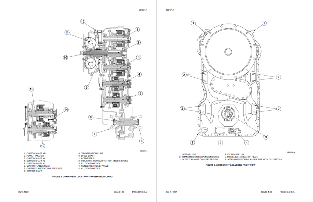
- Transmission
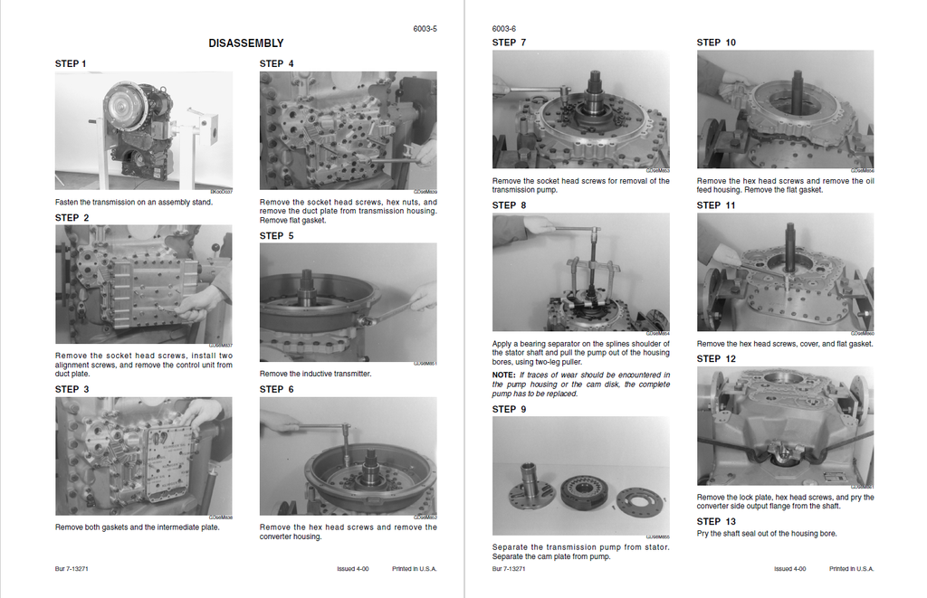
- Disassembly
- Assembly
- Front and Rear Axle
- Specifications
- Special Torques
- Special Tools
- Planetary Disassembly
- Planetary Assembly
- Planetary Hub Bearing Preload Procedure
- Brake Service on Axle Housing
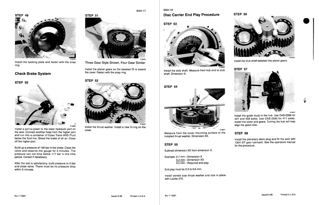
- Brake Disc Clearance Procedure
- Check Brake System
- Differential Removal and Disassembly
- 407 Differential Disassembly
- 409 and 411 Differential Disassembly
- Differential Assembly and Installation
- Differential Cover Clearance Procedure
- Pinion Shaft Bearing Preload Procedure
- Ring Gear Tooth Pattern Procedure
- Ring and Pinion Shim Procedure
- Check Brake Disc Wear - On Axle
- Drive Shaft, Center Bearing, and Universal Joints
- Special Torques
- Front Drive Shaft
- Removal
- Installation
- Center Bearing
- Removal
- Installation
- Center or Rear Drive Shaft
- Removal
- Installation
- Sliding Yoke
- Removal
- Installation
- Universal Joint
- Removal
- Installation
- Wheels and Tires
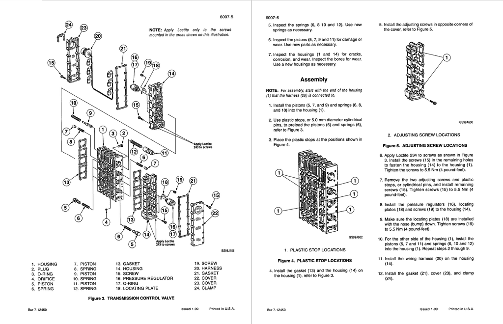
- Transmission Control Valve
- HYDRAULICS
- Testing and Adjusting the Pressure for the Unloader Valve
- Pressure Check
- Adjustment
- Hydraulic Component Locations
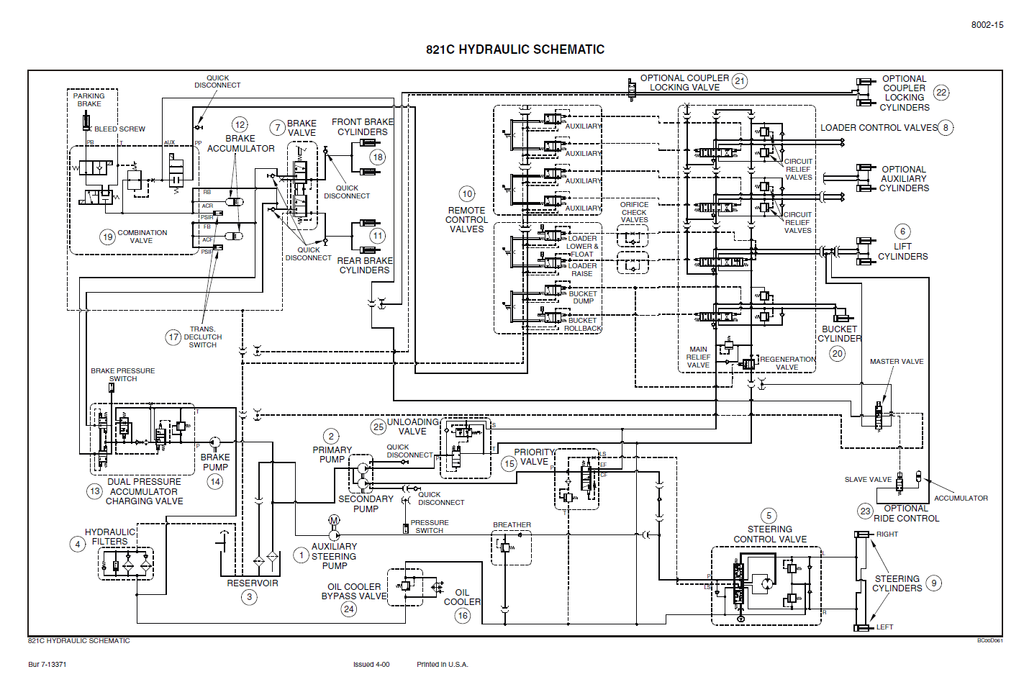
- 821C Hydraulic Schematic
- Troubleshooting the Steering System
- Problem in All Loader Circuits
- Problem in the Braking Circuit
- Problem in a Single Loader Circuit
- Problem in the Steering Circuit
- Testing the Hydraulic Pump
- Test No. 1 - Primary Pump Output Test
- Test No. 2 - Secondary Pump Output Test
- Cleaning the Hydraulic System
- Portable Filter
- General Information
- Types of Contamination
- Cleaning the Hydraulic System
- Flushing Water from the Hydraulic System
- Hydraulic Pump
- Specification
- Special Torques
- Hydraulic Pump
- Disassembly
- Assembly
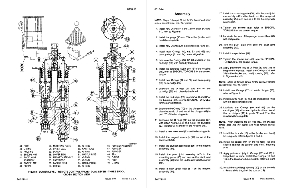
- Loader Control Valve
- Specifications
- Special Torques
- Separating the Valve Sections
- Disassembly
- Assembly
- Bucket and Auxiliary Sections
- Disassembly
- Inspection
- Assembly
- Lift Section
- Disassembly
- Inspection
- Assembly
- Regeneration Valve
- Disassembly
- Assembly
- MOUNTED EQUIPMENT
- Pedals and Levers
- Specifications
- Accelerator Pedal and Cable Adjustment
- Parking Brake
- Checking the Parking Brake
- Adjusting the Parking Brake
- Brake Pedals
- Air Conditioning Troubleshooting and System Checks For Systems With HFC-134a Refrigerant
- Safety Procedures
- Special Tools
- Operation
- Troubleshooting
- Problem: No Cooling
- Problem: Not Enough Cooling
- Problem: Erratic Cooling
- Problem: System Makes Noise
- System Checks
- Mechanical Compressor Check
- Blower and Compressor Clutch Check
- Cab Temperature Check
- Visual and Leak Check
- Evaporator/Heater Core Check
- Pressure Testing
- Manifold Gauge Set
- Pressure Test Connection
- Pressure-Temperature Chart
- A/C Recovery and Charging Station Connections
- Quick Reference Troubleshooting Chart
- Problem: No Cooling
- Problem: Not Enough Cooling
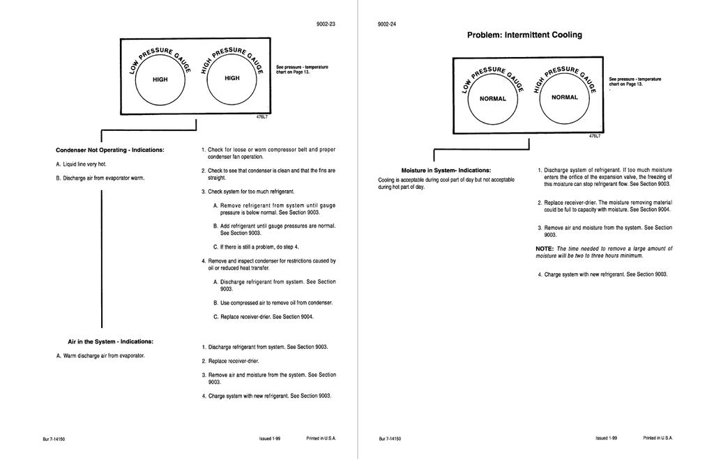
- Problem: Intermittent Cooling
- Problem: Noise in System
- Tube Connections Torque Chart
- Air Conditioner System Service
- Specifications
- Special Tools
- Safety Procedures
- Air Conditioner System Refrigerant Recovery
- Air Conditioner System Evacuation and Recharging
- Pressure-Temperature Chart
- Removal and Installation of Air Conditioning Components For Systems With HFC-134a Refrigerant
- Specifications
- Safety Procedures
- Special Tools
- Compressor Removal
- Compressor Installation
- Expansion Valve
- Removal
- Installation
- Control Valve
- Removal
- Installation
- Evaporator / Heater Core
- Removal
- Installation
- Condenser
- Removal
- Installation
- Air Conditioning Compressor and Clutch For Systems With HFC-134a Refrigerant
- Specifications
- Special Torques
- Special Tools
- Safety Procedures
- Compressor Belt Check and Adjustment
- Compressor Oil Level Check
- Compressor Repair
- Clutch Disassembly
- Illustration of Clutch Assembly
- Loader
- Specifications
- Standard Bucket
- Replacing the Cutting Edge
- Bucket Teeth
- Replacement of the Tooth Points
- Replacement of the Bucket Teeth
- Return-To-Dig Adjustment
- Return-To-Travel Adjustment
- Bucket Height Control Adjustment
- Removing the Loader Frame
- Installing the Loader Frame
- ROPS Cab and ROPS Canopy
- Specifications
- Possible Damage to the ROPS Cab or ROPS Canopy
- Maintenance and Inspection of the ROPS Cab or ROPS Canopy
- Removing the ROPS Cab or ROPS Canopy
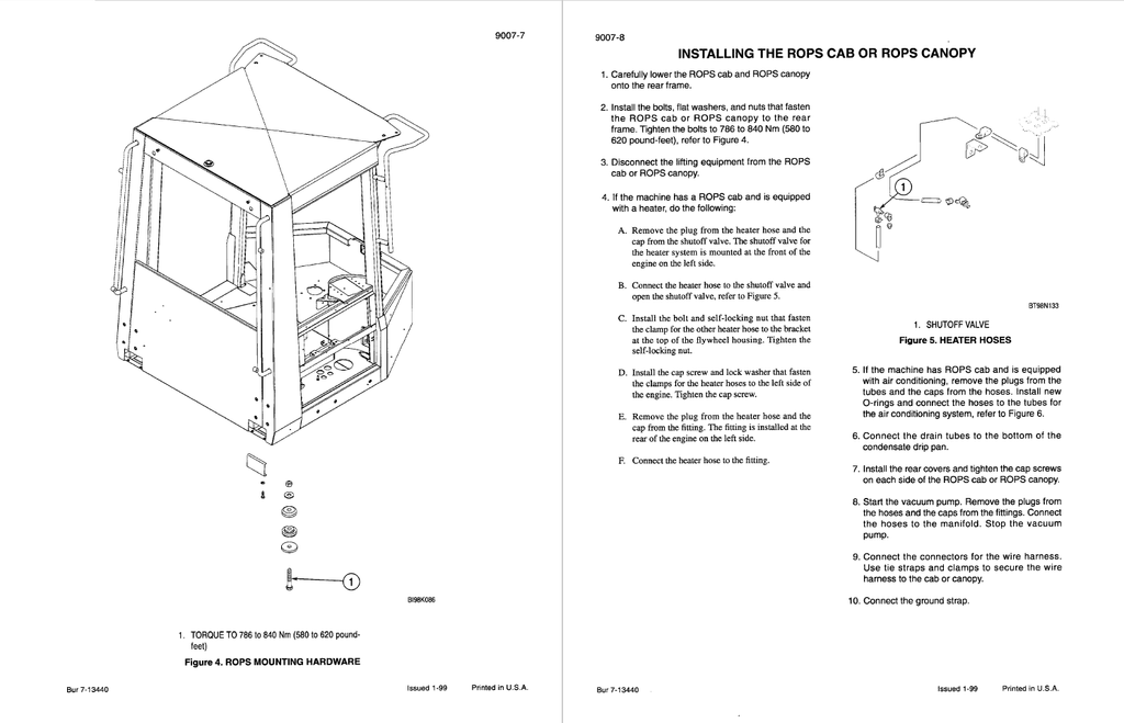
- Installing the ROPS Cab or ROPS Canopy
- Cab Glass Installation
- Preparation for Glass Replacement
- Glass Installation
- Silicone Sealant Application - Front Windows
- Pedals and Levers
- Testing and Adjusting the Pressure for the Unloader Valve