

CASE Construction 921C Wheel Loader Service Manual 7-12752, 7-13502 English
Official Manual Overview
Take absolute command of your heavy earthmoving operations with this definitive OEM Service Manual explicitly compiled for the CASE 921C Wheel Loader. Engineered for elite shop technicians, this massive volume goes far beyond basic maintenance to deliver micro-tolerance overhaul protocols for the entire drivetrain and hydraulic matrix. It provides surgical teardown procedures for the Denison tandem vane hydraulic pump and Husco four-spool loader control valves, alongside precision gear tooth contact pattern adjustments for the heavy-duty differential carrier (involving extreme 1877-1985 Nm axle mounting torques). Unprecedented diagnostic depth is also included for the ZF Transmission Electronic Control Module (ECM), featuring exact clutch calibration logic, as well as testing procedures for the 800-psi nitrogen-charged brake accumulators. Please note: Following the manufacturer's strict publication architecture, while chassis, hydraulic, and electrical metrology are exhaustively covered, internal diesel engine machining and fuel system overhauls are explicitly redirected to a dedicated Cummins Engine Service Center.
- Brands: CASE Construction
- Equipment Type: Wheel Loader
- Manuals Type: Service Manual
- Machine Model: 921C
- Serial Number: All Serial Numbers
- Region: N/R
- Book Code: 7-12752, 7-13502
- Issued: Printed in U.S.A. December, 2001
- Language: English
- Pages: 760
- File Format: PDF (Searchable)
Core Selling Points
- Precision Hydraulic Metrology & Calibration: Move beyond basic fluid changes with factory-mandated calibration procedures. This manual dictates the exact use of the CAS-1808 Flowmeter Kit and CAS-2702 adapters to verify system health, detailing absolute benchmarks such as the 184 to 193 bar (2665 to 2800 psi) pressure setting for the steering relief valve and minimum auxiliary pump outputs of 24 L/min.
- Micro-Tolerance Drivetrain Teardowns: Execute heavy mechanical overhauls with absolute mathematical certainty. The documentation provides surgical clearance data, requiring technicians to adjust the sun gear shaft end play to a strict 0.5 to 2.0 mm (0.02 to 0.08 inch) threshold, and shim the center pivot plates to achieve a precise 0.08 to 0.10 mm (0.003 to 0.004 inch) gap measurement.
- Unrestricted CAN-Bus & EIC Network Access: Transform your shop into a digital command center. Gain access to the full matrix of Information and Diagnostic Center fault codes, mapping out corrective actions for complex electronic failures ranging from Code 46229 (Error at communication on CAN) to critical TCU logic faults and RAM failures (Code 86050).
Features & Highlights
- ZF Transmission Diagnostics & Matrix Overhaul: Contains an exhaustive breakdown of the transmission control valve, clutch carriers, and planetary gears. It features a complete shifter logic information matrix, detailing exact terminal voltages and wire colors, alongside mandatory pressure testing protocols demanding 16 to 18 bar (230 to 265 psi) across all clutches (K1 through KV).
- Heavy-Duty Cylinder Reconstruction: Features specialized chapters dedicated to the lift and bucket cylinders, outlining the correct extraction of self-aligning bushings, wipers, and U-cup seals. Reassembly integrity is guaranteed with specific high-torque requirements, such as torquing the lift cylinder gland cap screws to 540 to 610 Nm (400 to 450 pound-feet).
- Deep Electrical Architecture & Topography: Eliminates blind circuit tracing with comprehensive connector cavity pinouts for Deutsch, AMP, Kostal, and Packard terminals. The manual specifies exact continuity targets and resistance values, such as verifying the engine oil pressure sender at exactly 38 ohms under a 5.2 Bar load.
- Advanced Braking System Overhaul: Details the uncompromising safety protocols required for the hydraulic braking matrix. It instructs technicians on the correct usage of the CAS-10899 Nitrogen Charging Kit to safely discharge and recharge the brake accumulators with dry nitrogen, ensuring the system meets the 11722 kPa low-pressure warning threshold.
Problem Solver
- Eradicates the "Parts Cannon" Diagnostic Approach: Stop replacing expensive sensors based on guesswork. The integrated hydraulic and torque converter stall test charts definitively isolate performance losses, using the exact 2100 to 2200 r/min hydraulic stall speed metric to immediately distinguish between a failing Denison pump and an underperforming engine block.
- Resolves Intermittent Electrical Gremlins: Provides dedicated troubleshooting matrices for every relay, solenoid, and proximity switch on the chassis. By testing against the factory voltage parameters and ground circuit continuities detailed here, technicians can permanently cure erratic bucket controls and phantom transmission declutch issues.
- Prevents Catastrophic Reassembly Failures: Improperly torqued pivot points or misaligned valve spools can destroy a machine within hours. This manual safeguards your labor with rigid "Do Not Ream" warnings for sintered bronze starter bushings, specific Loctite application charts, and mandatory gear tooth contact pattern alignments to ensure lasting repairs.
Important Pre-Purchase Advisories
- Engine Service Redirection: In strict accordance with CASE Corporation's publication strategy, this manual comprehensively covers engine removal, installation, and chassis interfaces. However, deep internal block machining, fuel injection pump timing, and internal diesel repairs are explicitly redirected to a certified Cummins Engine Service Center.
- Diagnostic Tooling Prerequisites: Certain advanced diagnostic procedures, particularly those involving transmission ECM recalibration and specific hydraulic flow tests, reference specialized proprietary OEM tools (e.g., CAS-10280 Flowmeter, CAS-2848 planetary gear puller).
Table of Contents
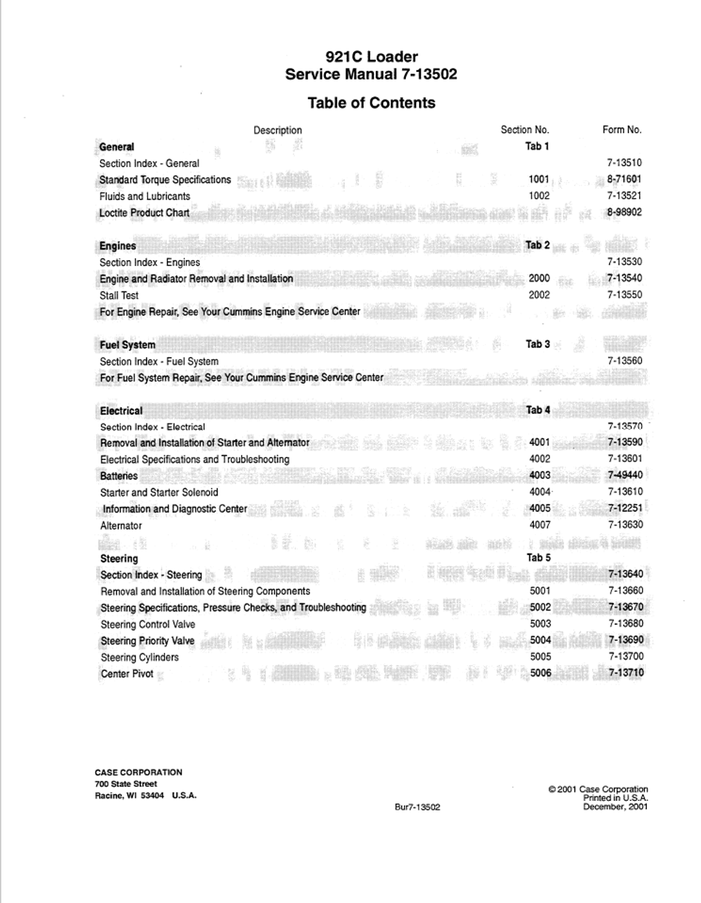
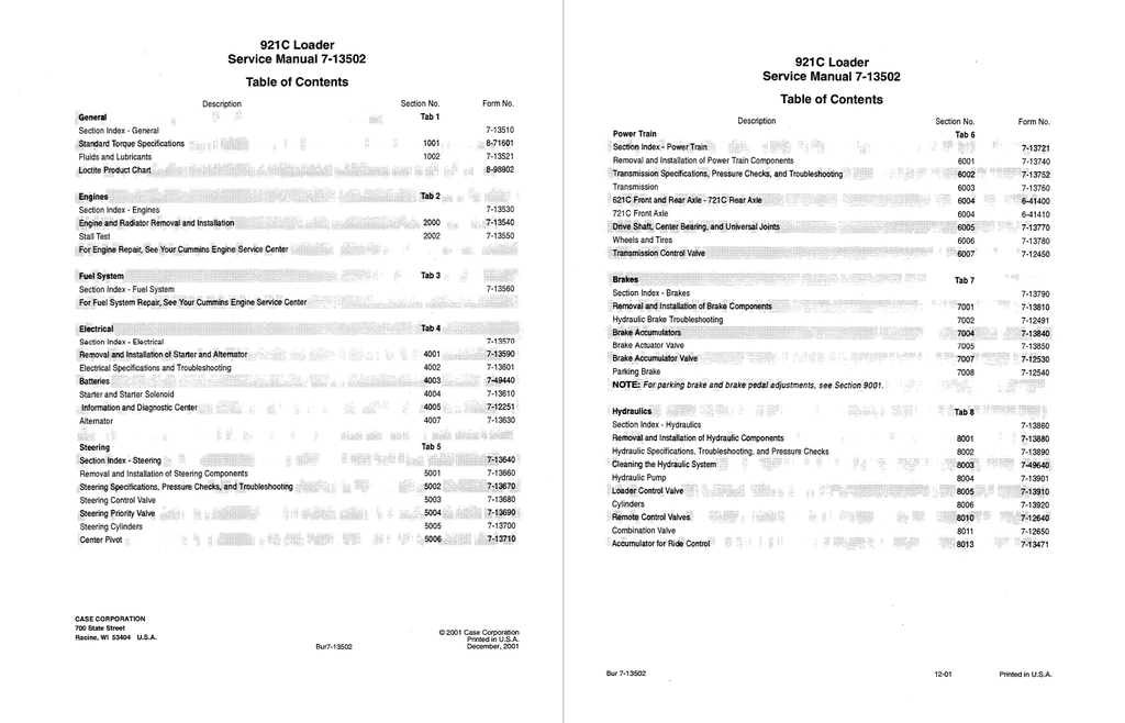
- General
- Standard Torque Specifications
- Fluids and Lubricants
- Capacities and Lubricants
- Engine Lubrication
- Diesel Fuel System
- Fuel Storage
- Specifications for Acceptable No. 2 Diesel Fuel
- Maintenance Schedule
- Loctite Product Chart
- Engines
- Engine and Radiator Removal and Installation
- Stall Test
- General Information
- Preparing the Machine for the Stall Test
- Procedure to Heat the Transmission Oil
- Procedure to Heat the Hydraulic Oil
- Test Procedure
- Check Sheet
- Electrical
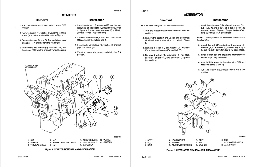
- Removal and Installation of Starter and Alternator
- Electrical Specifications and Troubleshooting
- Troubleshooting Batteries, Fuel Shutoff, Charging, Starting, Alternator, Cold Start, Ignition Switch and Relays
- Troubleshooting Ignition Relay, Accessory Relay, Voltmeter Relay, and Time Delay Module
- Troubleshooting Transmission Solenoids, Sensors and Switches, Control Module, Shifter, Diagnostic Connector, and Back-Up Alarm
- Troubleshooting Indicator Switches and Senders, Program Reset Switch, Park Brake Switch, Instrument Cluster, Pilot Control Switch, and Up/Down Count Switch
- Troubleshooting Engine Oil Pressure Sender, Pilot Control, Parking Brake, Engine Automatic Shutdown Relay, and Redundant Brake Switches
- Troubleshooting Bucket Controls
- Troubleshooting Secondary Steering Components and Ride Control
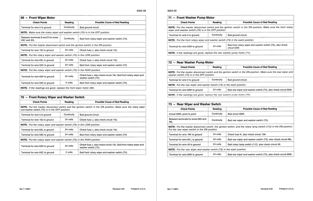
- Troubleshooting Wiper/Washer
- Troubleshooting Horn, Blower, Air Conditioning, and Condenser Fans
- Troubleshooting Cigar Lighter, Power Converter, Power Outlet, Radios and Speakers
- Troubleshooting Rotating Beacon, Stop Switch, Hazard Switch, Turn Signal/Hi/Low Beam/Horn Switch, and Flasher Module
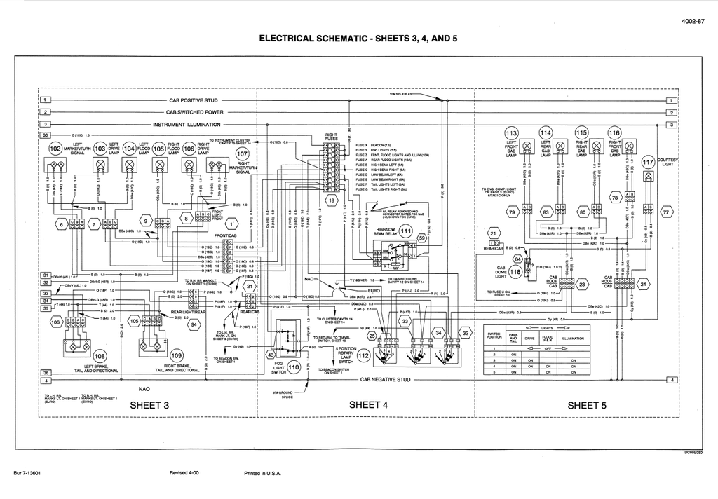
- Troubleshooting External Lights and Signals, Rotary Lamp Switch, and Cab Lights
- Troubleshooting External Lights and Signals, European Models
- Connectors
- Electrical Schematic
- Batteries
- Starter and Starter Solenoid
- No-Load Test
- Starter Solenoid Tests
- Starter Disassembly, Inspection, Tests, and Assembly
- Starter Solenoid Disassembly and Assembly
- Information and Diagnostic Center
- Self-Test
- Power Circuit Test
- Indicators and Gauges
- Warning Displays
- Information and Diagnostic Center
- Settings, Diagnostics, and Fault Codes
- Display Location Numbers and Descriptions
- Fault Codes
- Alternator
- Steering
- Removal and Installation of Steering Components
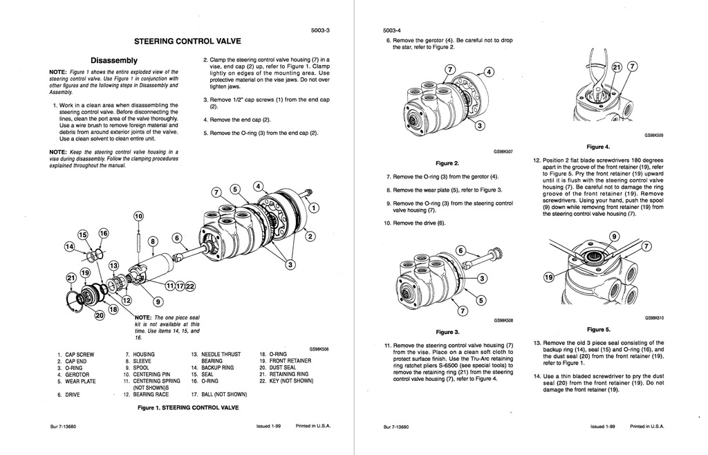
- Steering Control Valve
- Priority Valve
- Auxiliary Steering Pump
- Steering Cylinder
- Steering Specifications, Pressure Checks, and Troubleshooting
- Auxiliary Steering System Pump Test
- Auxiliary Steering System Motor Test
- Understanding the Results of the Test
- Steering Relief Valve Pressure Test
- Steering Relief Valve Pressure Adjustment
- Steering Cylinder Leak Test
- Steering Control Valve
- Disassembly
- Assembly
- Steering Priority Valve
- Steering Cylinders
- Disassembly
- Inspection
- Assembly
- Center Pivot
- Disassembly
- Assembly
- Assembly of Bearings for the Upper Pivot Pin
- Assembly of Bearings for the Lower Pivot Pin
- Connecting the Front Frame to the Rear Frame
- Removal and Installation of Steering Components
- Power Train
- Removal and Installation of Power Train Components
- Front Axle
- Rear Axle and Trunnions
- Differential Carrier
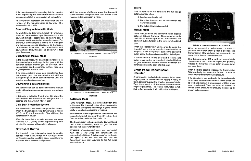
- Transmission
- Transmission Control Valve
- Transmission Specifications, Pressure Checks, and Troubleshooting
- Transmission Operation
- Transmission Pressure Test Points Diagram
- Chart for Recording Pressure Readings
- Pressure Test Results
- Converter Out Pressure Check
- Lubrication Pressure Check
- Flowmeter Test
- Consumption Test Procedure
- Transmission Overheating
- Error Codes
- Transmission Shifter Logic Information
- Relationship Between Transmission ECM, Valves, and Clutches
- Transmission Electrical Schematic
- Transmission
- Transmission Disassembly
- Forward and First Clutch Disassembly
- Clutch Carrier Assembly
- Clutch Disc Clearance Adjustment
- Forward and First Clutch Assembly
- Second and Reverse Clutch Disassembly
- Second and Reverse Clutch Assembly
- Third and Fourth Clutch Disassembly
- Third and Fourth Clutch Assembly
- Charge Pump Disassembly
- Charge Pump Assembly
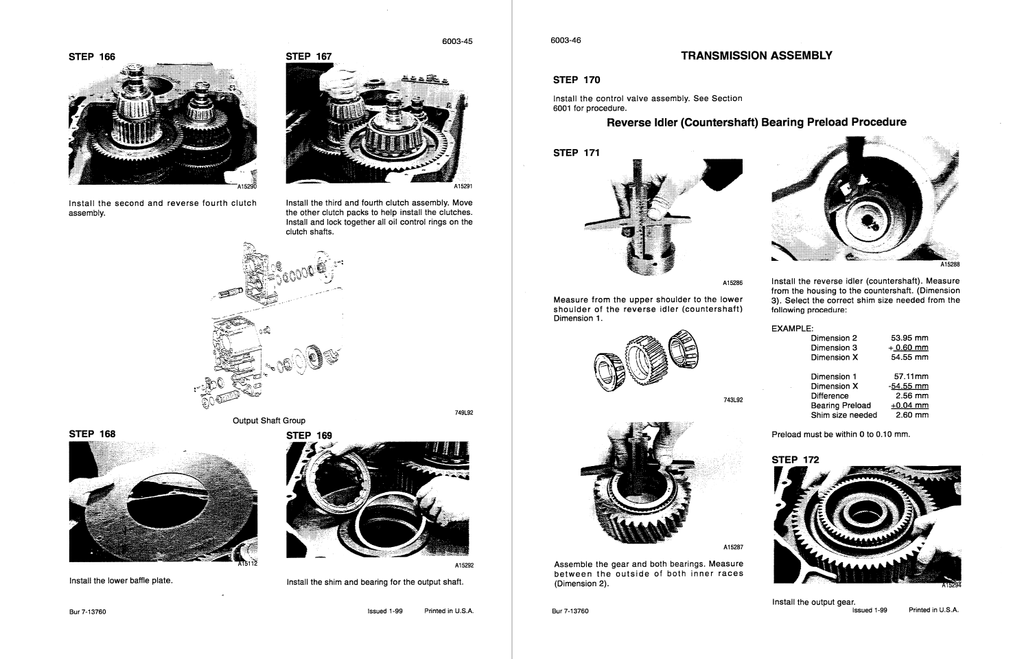
- Transmission Assembly
- Front and Rear Axle
- Gear Tooth Contact Patterns
- Lubrication Points
- Wear Measurement on Multi-Disc Brake
- Wheel End and Brake
- Leakage Test of the Brake Hydraulics
- Disassembly of Differential Carrier and Brake Tubes
- Disassembly of Limited Slip Differential
- Disassembly of Drive Pinion
- Disassembly of Brake Tubes
- Reassembly of Brake Tubes and Differential Carrier
- Reassembly of Differential Carrier
- Determine Shim Thickness for a Perfect Tooth Contact Pattern
- Install the Drive Pinion
- Adjust Rolling Moment of Drive Pinion Bearing
- Reassembly of Limited Slip Differential
- Adjust Backlash and Bearing Preload
- Drive Shaft, Center Bearing, and Universal Joints
- Front Drive Shaft
- Center Bearing
- Center or Rear Drive Shaft
- Sliding Yoke
- Universal Joint
- Wheels and Tires
- Transmission Control Valve
- Disassembly
- Inspection
- Assembly
- Removal and Installation of Power Train Components
- Brakes
- Removal and Installation of Brake Components
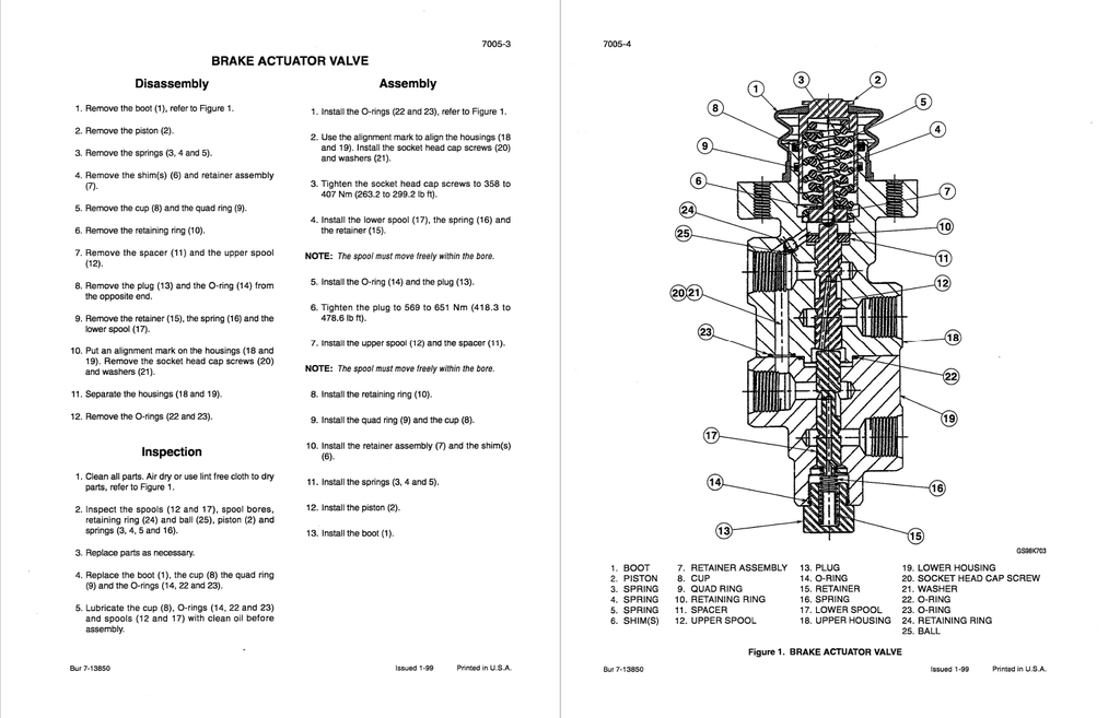
- Brake Actuator Valve
- Brake Accumulators
- Accumulator Valve
- Brake Pump
- Hydraulic Brake Troubleshooting
- Troubleshooting the Hydraulic Brake System
- Checking the Nitrogen Charge in the Accumulator
- Charging the Accumulator with Dry Nitrogen
- Accumulator Charge Valve Hydraulic Pressure Test
- Adjusting the Accumulator Charge Valve
- Bleeding the Brake System
- Brake Pump Output Test
- Brake Accumulators
- Discharging the Nitrogen Charge on an Accumulator
- Disassembly
- Assembly
- Brake Actuator Valve
- Disassembly
- Inspection
- Assembly
- Brake Accumulator Valve
- Disassembly
- Inspection
- Assembly
- Parking Brake
- Removal and Disassembly
- Assembly and Installation
- Warm Up
- Test
- Removal and Installation of Brake Components
- Hydraulics
- Removal and Installation of Hydraulic Components
- Removal and Installation of Loader Control Valve
- Removal and Installation of Remote Control Valve
- Removal and Installation of Hydraulic Pump
- Removal and Installation of Combination Valve
- Removal and Installation of Lift Cylinder
- Removal and Installation of Bucket Cylinder
- Removal and Installation of Oil Cooler
- Hydraulic Specifications, Troubleshooting, and Pressure Checks
- Troubleshooting Procedures
- Hydraulic Component Locations
- Hydraulic System Schematic
- Cleaning the Hydraulic System
- Portable Filter
- General Information
- Types of Contamination
- Cleaning the Hydraulic System
- Flushing Water From the Hydraulic System
- Hydraulic Pump
- Disassembly
- Inspection
- Assembly
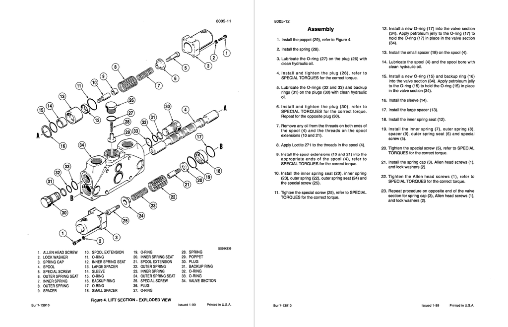
- Loader Control Valve
- Separating the Valve Sections
- Bucket and Auxiliary Sections
- Lift Section
- Regeneration Valve
- Main Relief Valve
- Circuit Relief Valve
- Circuit Relief and Anticavitation Valve
- Cylinders
- Lift Cylinder
- Bucket Cylinder
- Replacing Bushings for the Bucket and Lift Cylinders
- Remote Control Valves
- Remote Control Valve - Three Spool - Triple Lever
- Remote Control Valve - Three Spool - Dual Lever
- Remote Control Valve - Two Spool - Dual Lever
- Remote Control Valve - Two Spool - Single Lever
- Auxiliary Remote Control Valve - Two Spool - Single Lever
- Remote Control Valve - Four Spool - Dual Lever
- Combination Valve
- Disassembly
- Inspection
- Assembly
- Accumulator for Ride Control
- Solenoid Valve and Accumulator Valve for Ride Control
- Solenoid Valve for Ride Control
- Accumulator Valve for Ride Control
- Removal and Installation of Hydraulic Components
- Mounted Equipment
- Pedals and Levers
- Accelerator Pedal Adjustment
- Parking Brake
- Brake Pedals
- Air Conditioning Troubleshooting and System Checks For Systems With HFC-134a Refrigerant
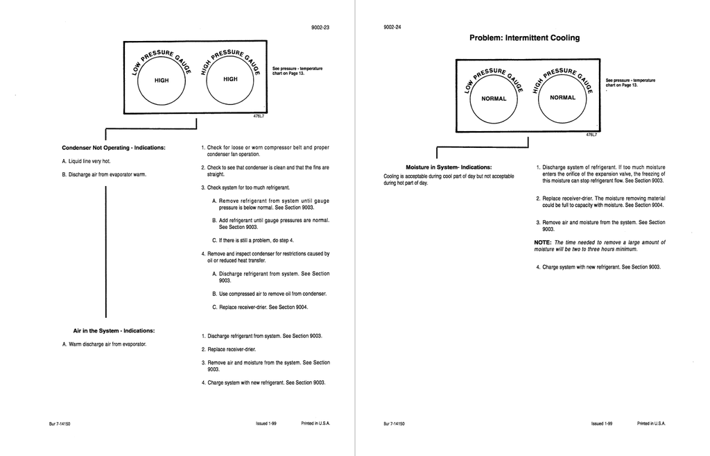
- Air Conditioner System Service
- Removal and Installation of Air Conditioning Components For Systems With HFC-134a Refrigerant
- Air Conditioning Compressor and Clutch For Systems With HFC-134a Refrigerant
- Safety Procedures
- Compressor Belt Check and Adjustment
- Compressor Oil Level Check
- Compressor Repair
- Loader
- Return-To-Dig Adjustment
- Bucket Height Control Adjustment
- Removing the Loader Frame
- ROPS Cab and ROPS Canopy
- Possible Damage to the ROPS Cab or ROPS Canopy
- Maintenance and Inspection of the ROPS Cab or ROPS Canopy
- Removing the ROPS Cab or ROPS Canopy
- Installing the ROPS Cab or ROPS Canopy
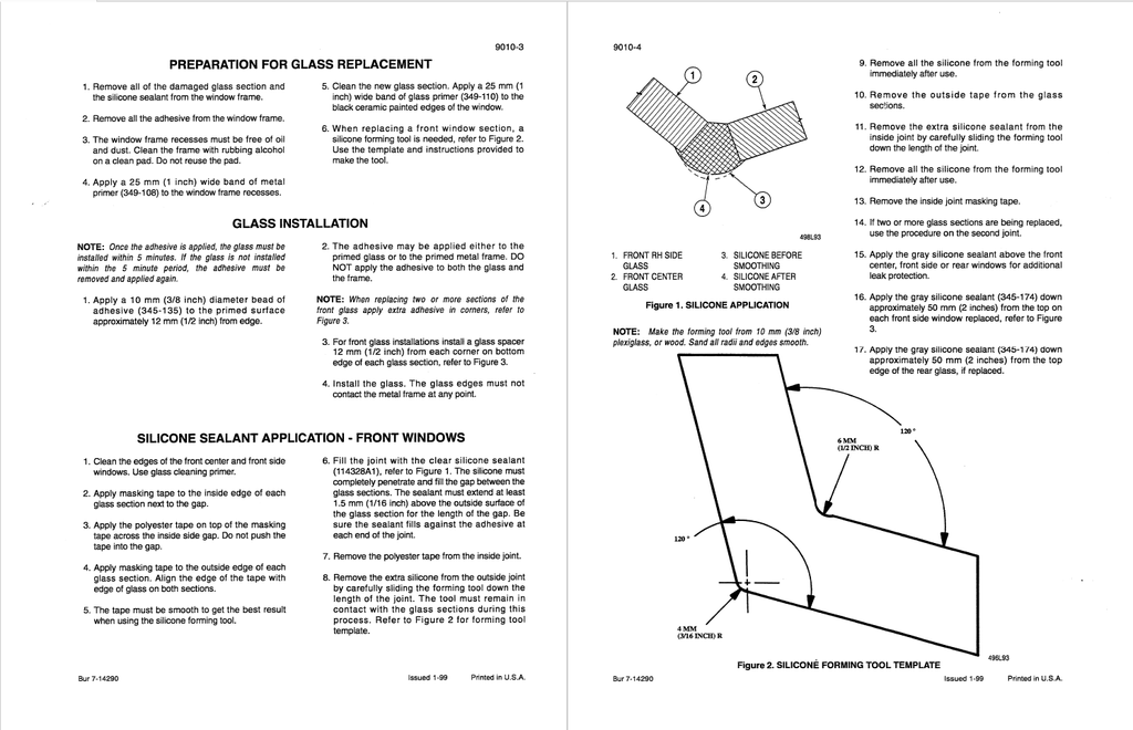
- Cab Glass Installation
- Preparation for Glass Replacement
- Glass Installation
- Silicone Sealant Application - Front Windows
- Pedals and Levers