

CASE Construction CB32, CB45, CB65, CB85, CB120, CB150, CB200 S, CB260 S, CB320 S, CB400 S, CB550 S, CB700 S Hydraulic Hammer Service Manual 6036722100, 603.67.221.00 English
Official Manual Overview
Equip your heavy-duty attachment rebuild facility with the definitive OEM Service Manual dedicated to the entire spectrum of CASE / CNH CB-Series Hydraulic Hammers (covering everything from the compact CB32 up to the massive CB700 S). Moving far beyond basic chisel replacement, this master blueprint delivers dealership-level hydraulic breaker reconstruction protocols. It dictates strict nitrogen (N2) gas charging procedures for the internal accumulators—demanding precisely 40 bar (580 psi) for the high-pressure circuits to restore maximum impact rhythm. Structural mechanics will find extreme fastening metrics engineered to withstand brutal vibration, enforcing an immense 1600 Nm torque for the CB120 chassis plates and a staggering 2100 Nm for the CB550 S housing retaining screws. Packed with proprietary flowmeter diagnostic routing, exact tool bushing wear limits (condemning the CB550 S thrust ring if worn past 11.3 mm), and complete control valve teardowns, this is the ultimate weapon to eradicate impact power loss and guarantee peak breaking force.
- Brands: CASE Construction
- Equipment Type: Hydraulic Hammer
- Manuals Type: Service Manual
- Machine Model: CB32, CB45, CB65, CB85, CB120, CB150, CB200 S, CB260 S, CB320 S, CB400 S, CB550 S, CB700 S
- Serial Number: N/R
- Region: N/R
- Book Code: 6036722100, 603.67.221.00
- Issued: Printed in France - January 2005
- Language: English
- Pages: 124
- File Format: PDF (Searchable)
Core Selling Points
- Extreme Kinetic Fastening & Thermal Torquing: Do not compromise the structural integrity of your breaker under brutal percussion. This master blueprint dictates the exact thermal-mechanical tie-rod tensioning sequences, instructing technicians to heat the rods to a strict maximum of 300°C before applying a 500 Nm baseline torque, followed by an exact 120-degree supplementary tightening angle on the CB260 S and CB320 S heavy-duty models.
- Precision Nitrogen Accumulator Calibration: Restore factory impact force safely. The documentation eliminates guesswork by providing the exact nitrogen (N2) charging procedures using the proprietary R050253 charging kit. It strictly mandates charging the high-pressure accumulators to 40 bar (580 psi) across all major models, while carefully balancing the low-pressure accumulators between 10 and 15 bar to prevent piston recoil failures.
- Micrometer-Level Component Condemnation: Scientifically evaluate front part degradation. The manual maps out absolute wear limit dimensions for the inner tool bushings and thrust rings, demanding the immediate replacement of the CB550 S thrust ring if it elongates past 11.3 mm, or if the upper tool bushing bore expands beyond 161.5 mm, effectively preventing catastrophic internal cylinder scoring.
Features & Highlights
- Advanced Flowmeter Diagnostic Routing: Master the fluid power dynamics of your attachment. The manual details dynamic testing using in-line flowmeters, mapping out dedicated hydraulic test ports to verify supply pressure (p2), ensure the return counter-pressure (p3) does not exceed limits, and monitor oil temperature (T2) simultaneously to guarantee the host machine is delivering the required 220–320 L/min for the massive CB700 S.
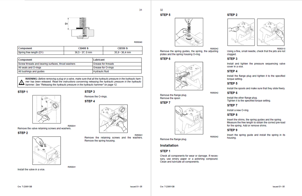
- Deep-Level Control Valve Reconstruction: Bypass superficial seal replacements. The literature guides mechanics through the total extraction and overhaul of the main control valve assembly. It provides step-by-step procedures for removing the directional and sliding bushings using extraction plates, ensuring precise spool tolerances and eliminating internal cross-port leakage.
- Proprietary Heavy-Duty Tooling Registries: Execute dealership-level overhauls without damaging delicate internal bores. The text details the exact usage of specialized OEM service equipment, such as the R050066 bushing extractor frame and hydraulic ram assembly, enabling technicians to safely press out lower tool bushings and separator pins without utilizing destructive cutting methods.
Problem Solver
- Resolves Decreased Impact Rhythm: Systematically eradicate sluggish hammer performance. The troubleshooting flowcharts train mechanics to look beyond basic piston wear, directing them to test for overheated hydraulic fluid (exceeding 80°C), incorrect oil viscosity (dropping outside the optimal 30-60 cSt range), or restricted return filters that cause extreme back-pressure and choke the hammer's BPM.
- Defeats "Dead Hammer" Stalling: Transform a completely unresponsive breaker into a calculated repair. If the hammer refuses to strike, the diagnostic logic tree isolates the root cause—guiding technicians to check if the piston is locked in the hydraulic brake position, clear excessive grease packing the tool contact area, or verify the safety relief valve setting before prematurely tearing down the cylinder.
- Eradicates Destructive Housing Vibration: Stop your hammer from destroying its own chassis. The guide details the inspection of the vibration damping system, mandating that the clearance between the hammer mechanism and the outer casing must be strictly maintained within -10 to 10 mm. It provides exact dimensional limits for the upper and lower buffer pads to ensure kinetic energy is transferred to the rock, not the excavator boom.
Important Pre-Purchase Advisories
- Host Machine Setup Exclusions: While this Service Manual provides complete hydraulic flow requirements and counter-pressure limits, it explicitly directs users to consult the separate Operator's Manual for specific tool-carrier (excavator) weight class compatibility and structural stability tables.
- Specialized Gas Handling: Please note that the accumulator overhaul procedures outlined in this documentation require the use of pure Nitrogen (N2) gas and dedicated high-pressure charging regulators to perform safely.
Table of Contents
- Hydraulic hammers CB32 - CB45 - CB65 - CB85 - CB120 - CB150
- TECHNICAL SPECIFICATIONS
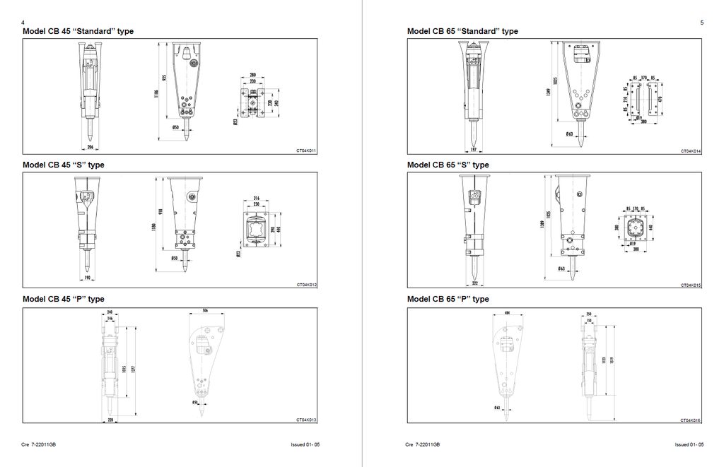
- Overall dimensions
- TORQUE SETTING
- HAMMER HYDRAULIC PRESSURE DISCHARGE
- LOCATION OF MAIN COMPONENTS
- Removing the chassis plates
- Installing the chassis plates
- Releasing pressure in the low pressure accumulator
- LOW PRESSURE ACCUMULATOR
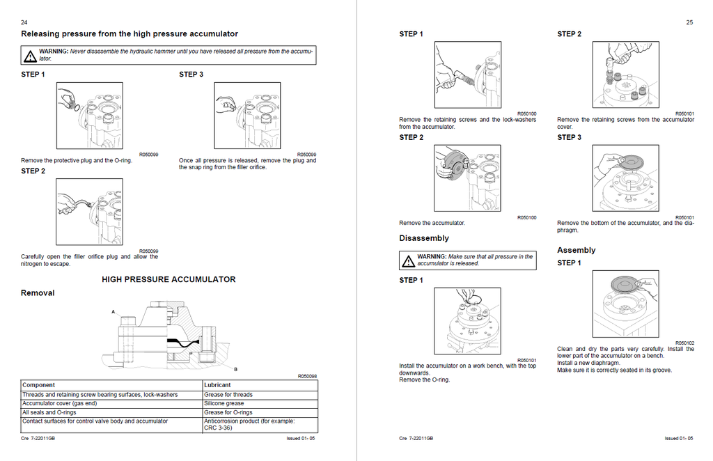
- Releasing pressure from the high pressure accumulator
- HIGH PRESSURE ACCUMULATOR
- Removal
- Disassembly
- Assembly
- CHARGING THE ACCUMULATOR
- Charging
- PRESSURE REGULATING VALVE
- Removal
- Adjustment
- Assembly
- TIE-RODS
- Removal
- CONTROL VALVE COMPONENTS (CB32 - CB85)
- Removal
- Installation
- CONTROL VALVE BODY COMPONENTS (CB45 - CB65 - CB120 - CB150)
- Removal
- Installation
- CYLINDER
- Removal
- Installation
- FRONT PART
- Removal
- Installation
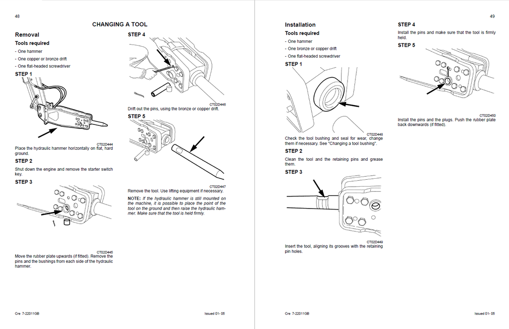
- CHANGING A TOOL
- Removal
- Installation
- CHANGING THE TOOL BUSHING
- Removal
- Installation
- WEAR LIMITS
- Tool bushings
- Tools
- INSPECTION AND MEASUREMENT OF HYDRAULIC HAMMER CIRCUIT
- Measurement/inspection points
- TROUBLESHOOTING
- TECHNICAL SPECIFICATIONS
- Hydraulic hammers CB200 S - CB260 S - CB320 S - CB400 S - CB550 S - CB700 S
- TECHNICAL SPECIFICATIONS
- Overall dimensions
- COMPONENT IDENTIFICATION
- LOCATION OF MAIN COMPONENTS
- HOUSING AND VIBRATION DAMPER
- Removal
- Installation
- PRESSURE ACCUMULATOR PRESSURE RELEASE
- PRESSURE ACCUMULATOR
- Removal
- Disassembly
- Installation
- CHARGING THE ACCUMULATOR
- DISCHARGE VALVE
- Removal
- Installation
- NON-RETURN VALVE
- PRESSURE REGULATOR
- Removal
- Installation
- PRESSURE SEQUENCING VALVE (CB400 S - CB550 S)
- Removal
- Installation
- TIE-ROD
- CONTROL VALVE BODY COMPONENTS (CB200 S - CB260 S - CB320 S)
- Removal
- Installation
- CB400 S - CB550 S
- FRONT PART
- Removal
- Installation
- CHANGING A TOOL
- Removal
- Installation
- CHANGING THE TOOL BUSHING
- Removal
- Installation
- WEAR LIMITS
- Types: CB200 S, CB260 S, CB320 S, CB400 S, CB550 S, CB700 S
- Tools
- INSPECTION AND MEASUREMENT OF HYDRAULIC HAMMER CIRCUIT
- Measurement/Inspection points
- TROUBLESHOOTING
- TECHNICAL SPECIFICATIONS