

CASE Construction CX130, CX130LC, CX130LR Crawler Excavator Service Manual 7-27353 English
Official Manual Overview
Maximize the breakout force and uptime of your 13-ton class earthmover with this definitive OEM Service Manual, engineered with a primary focus on the CASE CX130 Crawler Excavator (including LC and LR variants). Designed for elite diagnostic technicians, this volume bypasses routine upkeep to deliver surgical teardown procedures specific to the CX130's architecture. It provides micro-tolerance overhaul data for the machine's exclusive Uchida double axial piston pump (ensuring the exact 2x123 L/min maximum flow is met) and dictates uncompromising torque specifications—such as the massive 3150 Nm required for the boom cylinder piston nut and the strict 392-430 Nm parameter for track pad installation. Furthermore, it transforms your workshop into a digital command center by detailing the exact monitor keystrokes needed to access hidden diagnostic menus, decode CAN-bus network errors (like Code M0090), and precisely calibrate the proportional solenoid amperages for the H/S/L auto-working modes. Please note: In strict adherence to the manufacturer's publication strategy, while the chassis, CAN-bus electrical networks, and complex hydraulics are exhaustively covered, deep internal Isuzu diesel engine block disassembly is explicitly redirected to a dedicated Engine Service Manual.
- Brands: CASE Construction
- Equipment Type: Crawler Excavator
- Manuals Type: Service Manual
- Machine Model: CX130, CX130LC, CX130LR
- Serial Number: All Serial Numbers
- Region: N/R
- Book Code: 7-27353
- Issued: Printed in France, May 2005
- Language: English
- Pages: 660
- File Format: PDF (Searchable)
Core Selling Points
- Dealership-Level Electrical Pinpointing: Abandon trial-and-error diagnostics. This manual equips technicians to utilize the CAS-30039 service connector kit and a multimeter to isolate faults down to the exact wire. It details precise continuity checks, such as testing the GrG wire between the S55 coolant level switch and the CN24 connector, or verifying a strict 24V output at the CN6 terminal 28 for the travel speed solenoid.
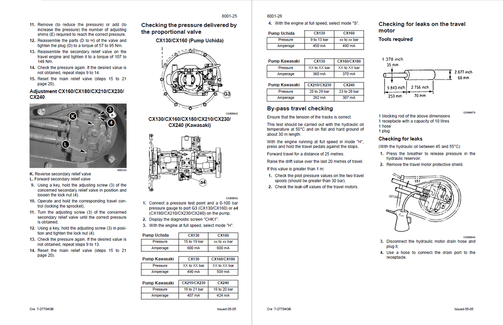
- Precision Hydraulic Metrology & Tooling: Master the machine’s complex fluid dynamics. The literature outlines mandatory calibration procedures using the Multi-Handy 2051 connecting cable and CAS 2764 flowmeters. It provides absolute pressure targets, instructing mechanics to tune the pilot system secondary relief valves to exactly 39±1 bar (3.9±0.1 MPa) and configure the main relief higher-pressure levels up to 373±5 bar (37.3±0.5 MPa).
- Strict Undercarriage & Linkage Metrology: Ensure structural longevity with exhaustive micrometer wear limits. The documentation moves beyond basic visual checks, demanding technicians verify the standard 171.45 mm track pitch and mandating replacement when the toothed wheel diameter reaches the absolute 53 mm limit. It also dictates precise shimming to maintain a strict 0.5 to 3 mm clearance at the boom-to-dipper connection.
Features & Highlights
- Deep-Level Digital Diagnostics (DIAG & CHK): Provides total mastery over the onboard Information and Diagnostic Center. It decodes complex fault matrices, walking users through accessing historical data (DIAG2/DIAG3) to resolve critical logic errors like E0031 (Linear motor control circuit faults) and M0010 (Transistor output short-circuits).
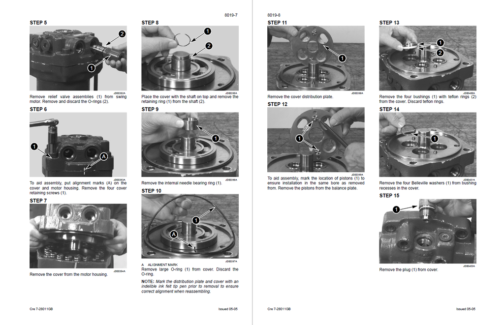
- Heavy Component Disassembly & Torque Architecture: Delivers surgical teardown protocols for critical assemblies, including the swing reduction gears, main control valves, and travel motors. Reassembly integrity is guaranteed through rigid fastening specifications, requiring 267 to 312 Nm of torque for the travel motor retaining screws and utilizing specialized Loctite 262 applications.
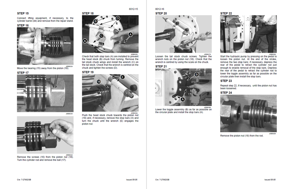
- Complete Cylinder Reconstruction: Outlines the safe extraction and rebuilding of high-pressure hydraulic cylinders using the OEM 9797 repair bench. To prevent catastrophic seal failure, it dictates massive torque parameters, such as applying up to 4820 Nm to the CX210 boom cylinder piston nut using the OEM 9798 tool.
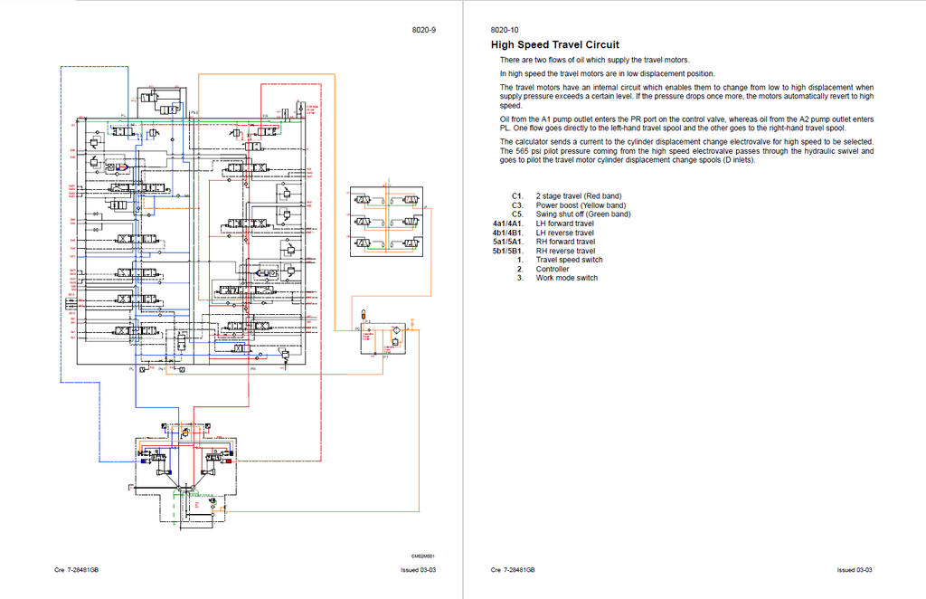
- Dynamic Circuit Mapping: Extensively charts the flow logic of specialized hydraulic networks. It breaks down the internal spool movements and valve operations for the High Speed Travel, Boom Lowering Anti-vibration, and Swing Priority circuits, making complex fluid troubleshooting straightforward.
Problem Solver
- Eradicates "Parts Cannon" Maintenance: Stop guessing which electronic module has failed. By testing the exact proportional solenoid amperage targets (e.g., verifying 600 mA in H-mode for the Uchida pump), technicians can definitively prove whether a performance drop is caused by a failing solenoid, a corrupted ECM, or a mechanical restriction.
- Cures Intermittent Power Loss: Resolves hidden hydraulic bypassing issues that cause sluggish operation. The manual details specific travel motor leak-off tests—measuring the exact oil volume drained over one minute while the sprocket is mechanically locked—to instantly isolate internal motor wear.
- Prevents Reassembly Catastrophes: Improperly torqued fittings or misaligned spools can destroy a heavy earthmover. This manual safeguards your labor with rigid step-by-step reassembly sequences, ensuring components like the dipper semi-parallel valve block and control pedal cams (requiring 13.3 to 16.1 Nm on the articulation pin) are rebuilt to exact factory tolerances.
Important Pre-Purchase Advisories
- Dedicated Engine Repair Not Included: In strict alignment with CASE Corporation's publication standards, this manual covers engine removal, installation, and chassis-side electronic interfaces. However, deep internal diesel engine block disassembly (such as piston/crankshaft removal) is explicitly redirected to the standalone Engine Service Manual.
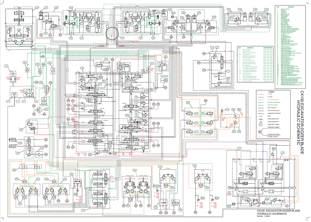
- Supplemental Schematics Note: While the manual provides extensive electrical and hydraulic troubleshooting charts and pinout data, the original factory publication included "Large format electrical and hydraulic schematics" as physical pocket inserts (e.g., Reference 9-88430).
- Specialized OEM Tooling Referenced: Certain advanced calibration and teardown procedures mandate the use of proprietary tools (e.g., CAS-10090 hand pump, PE-174E-220 hydraulic pump) to safely execute the repairs as described.
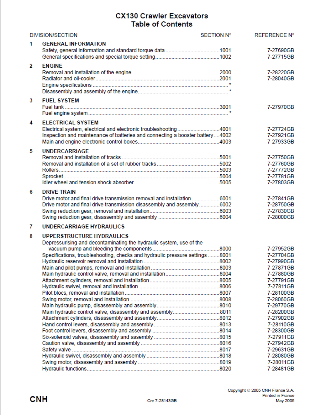
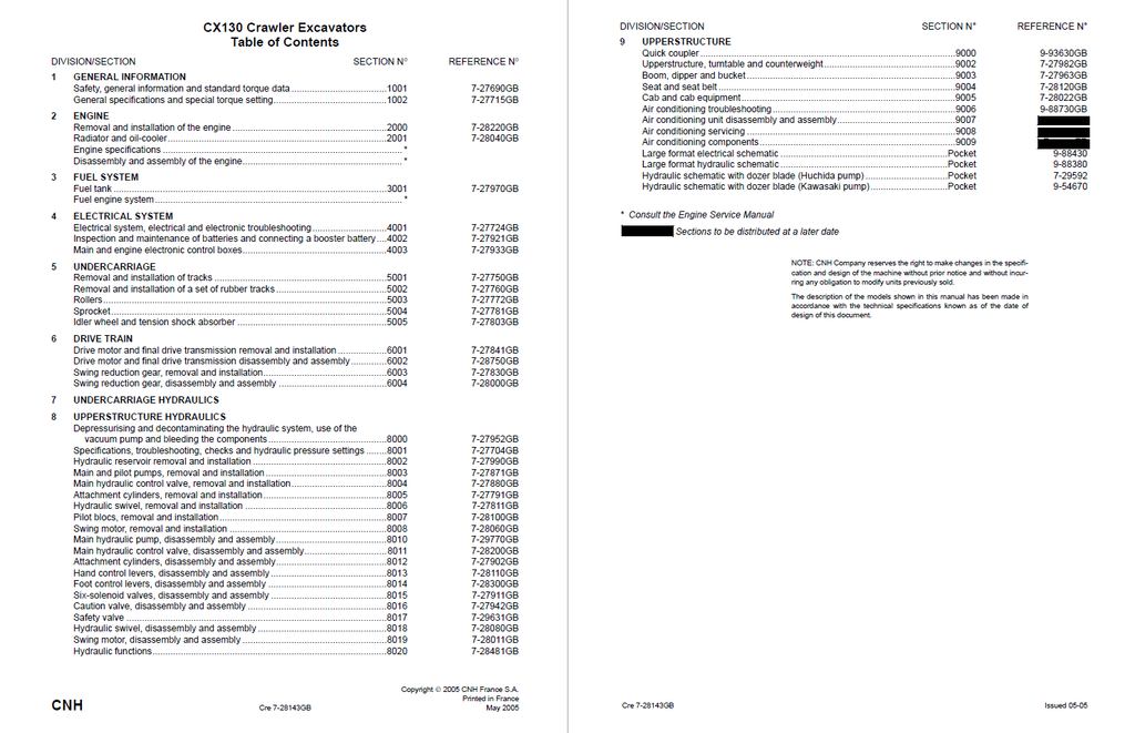
Table of Contents
- General Information
- Safety, general information and standard torque data
- General information
- Safety
- Standard torque data for cap screws and nuts
- General specifications and special torque setting
- Type, serial number and year of manufacture of the machine
- Machine
- Engine
- Component serial numbers
- Fluids and lubricants
- Hydraulic fluid
- Transmission component oil
- Grease
- Engine oil
- Oil viscosity/Oil range
- Fuel
- Anti-freeze/Anti-corrosion
- Environment
- Components made from plastic or resin
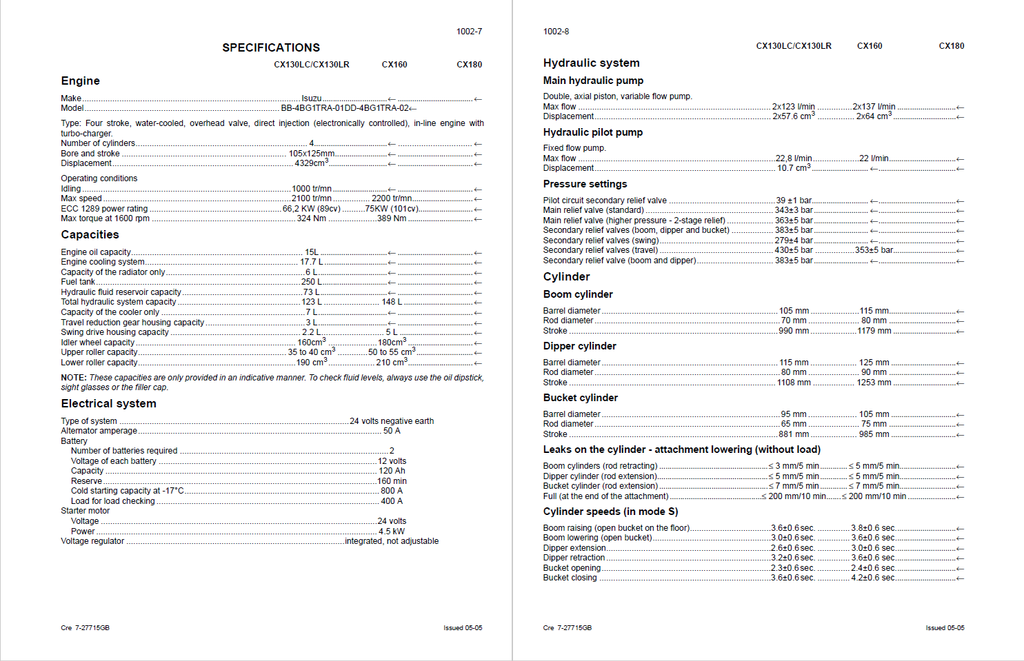
- Specifications
- Engine
- Capacities
- Electrical system
- Hydraulic system
- Cylinder
- Control valve
- Swing
- Travel
- Undercarriage
- Attachment
- Weight of components
- Dimensions and limit of wear and tear of the tracks set
- Toothed wheel
- Idler wheel
- Upper roller
- Lower roller
- Track
- Dimensions and limit of wear and tear of the mobile joints of the attachment
- Boom foot/Undercarriage
- Boom cylinder foot/Undercarriage
- Boom cylinder head/Boom
- Dipper cylinder foot/Boom
- Boom/Dipper
- Dipper cylinder head/Dipper
- Bucket cylinder foot/Dipper
- Connecting rod/Dipper
- Compensator/Bucket
- Connecting rod/Compensator/Bucket cylinder head
- Dipper/Bucket
- Special torque settings
- Machine overall dimensions CX130LC/CX160
- Machine overall dimensions CX130LR
- Machine overall dimensions CX180
- Type, serial number and year of manufacture of the machine
- Safety, general information and standard torque data
- Engine
- Removal and installation of the engine
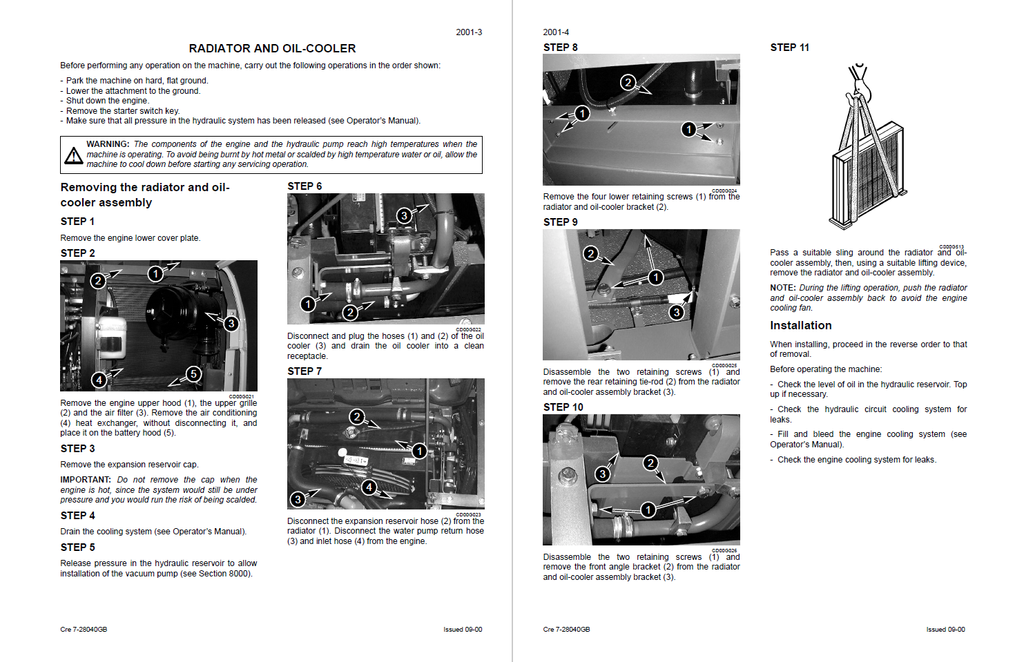
- Radiator and oil-cooler
- Specifications
- Radiator and oil-cooler
- Removing the radiator and oil-cooler assembly
- Installation
- Fuel System
- Fuel tank
- Specifications
- Fuel reservoir
- Removal
- Installation
- Description
- Fuel tank
- Electrical System
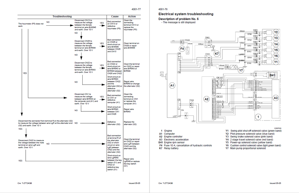
- Electrical system, electrical and electronic troubleshooting
- Specifications
- Special tools
- Location of components
- General location of the components (outside the cab)
- Relay and main fuses (battery compartment)
- General location of the components (inside the cab)
- Fuse box
- Instrument panel
- Operating principles
- Engine checks
- Work mode selection
- H/S/L mode checking
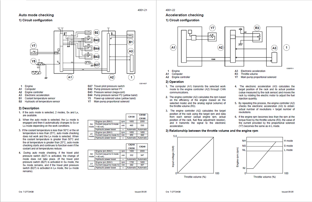
- Auto mode checking
- Acceleration checking
- Engine idle checking (automatic/manual)
- Breaker mode checking
- Automatic engine preheat
- Fuel level
- Engine fuel injection pump electronic regulator
- Access and contents of monitor displays (Diagnostic mode)
- Access to monitor displays
- Machine condition
- Diagnostic code
- Machine history
- Re-initialisation
- Warning messages
- Message display
- Excavator model selection procedure
- Changing the language code
- Changing the access code for the anti-theft system
- Troubleshooting
- Prior inspections
- Reading the organisation charts
- Procedures
- Low fuel
- Add coolant solution
- Travel
- Electrical inspection of components
- Inspection equipment
- Proportional solenoid
- Engine emergency stop motor
- 6 solenoid valve block
- Engine rpm sensor
- Engine coolant and hydraulic oil temperature sensor
- Pressure sensor
- Inspection and maintenance of batteries and connecting a booster battery
- Safety instructions
- Specifications
- Main and engine electronic control boxes
- Main electronic control box and engine electronic control box
- Removal
- Main electronic control box
- Engine electronic control box
- Installation
- Main electronic control box and engine electronic control box
- Electrical system, electrical and electronic troubleshooting
- Undercarriage
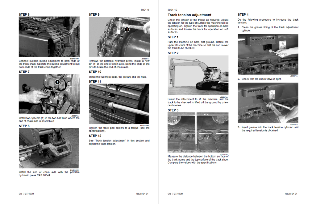
- Removal and installation of tracks
- Removal and installation of a set of rubber tracks
- Rollers
- Special torque settings
- Special tools
- Lower roller
- Description
- Removal
- Reconditioning
- Disassembly
- Inspection
- Assembly
- Installation
- Upper roller
- Description
- Removal
- Reconditioning
- Disassembly
- Inspection
- Sprocket
- Idler wheel and tension shock absorber
- Disassembly and assembly of the idler wheel
- Description
- Reconditioning
- Disassembly
- Inspection
- Assembly
- Leakage test
- Disassembly and assembly of the tension shock absorber
- Description
- Disassembly
- Assembly
- Track tension cylinder (CX130, CX160, CX180, CX230 and CX240)
- Description
- Removal
- Disassembly
- Inspection
- Assembly
- Installation
- Track tension cylinder (CX180, CX210)
- Description
- Removal
- Disassembly
- Inspection
- Assembly
- Disassembly and assembly of the idler wheel
- Drive Train
- Drive motor and final drive transmission removal and installation
- Specifications
- Special torques
- Drive motor and final drive transmission
- Removal and installation
- Drive motor and final drive transmission disassembly and assembly
- Specifications
- Special torques
- Drive motor and final drive transmission
- Disassembly
- Inspection
- Swing reduction gear, removal and installation
- Swing reduction gear, disassembly and assembly
- Drive motor and final drive transmission removal and installation
- Upperstructure Hydraulics
- Depressurising and decontaminating the hydraulic system, use of the vacuum pump and bleeding the components
- Special tools
- Releasing pressure in the hydraulic system
- Bleeding air from the main hydraulic system components
- Hydraulic pump
- Attachment cylinders
- Hydraulic swing motor
- Vacuum pump
- Installation
- Specifications, troubleshooting, checks and hydraulic pressure settings
- Specifications
- Special tools
- Tester
- Identification of hydraulic components
- Pump CX130/CX160 (Uchida)
- Pump CX130/CX160/CX180/CX210/CX230/CX240 (Kawasaki)
- Control valve CX130/CX160/CX180
- Control valve CX210/CX230/CX240
- 6 solenoid valve manifold
- Display on diagnostic screen "CHK1"
- Warming up the engine
- Warming up the hydraulic fluid
- Checking and pressure setting procedure
- Hydraulic reservoir removal and installation
- Main and pilot pumps, removal and installation
- Main hydraulic pump
- Removal and installation
- Pilot pump
- Removal and installation
- Main hydraulic pump
- Main hydraulic control valve, removal and installation
- Specifications
- Special torque settings
- Attachment cylinders, removal and installation
- Specifications
- Preparation before removal/installation
- Boom cylinder
- Description
- Removal
- Installation
- Dipper cylinder
- Description
- Removal
- Installation
- Bucket cylinder
- Description
- Hydraulic swivel, removal and installation
- Pilot blocs, removal and installation
- Pilot function blocks
- Travel pedal block
- LH control lever
- RH control lever
- Swing shuttle block
- Cushion control valve
- Servo control and return manifold block
- 6 solenoid valve block
- Pilot function blocks
- Swing motor, removal and installation
- Special torque settings
- Swing motor
- Removal and installation
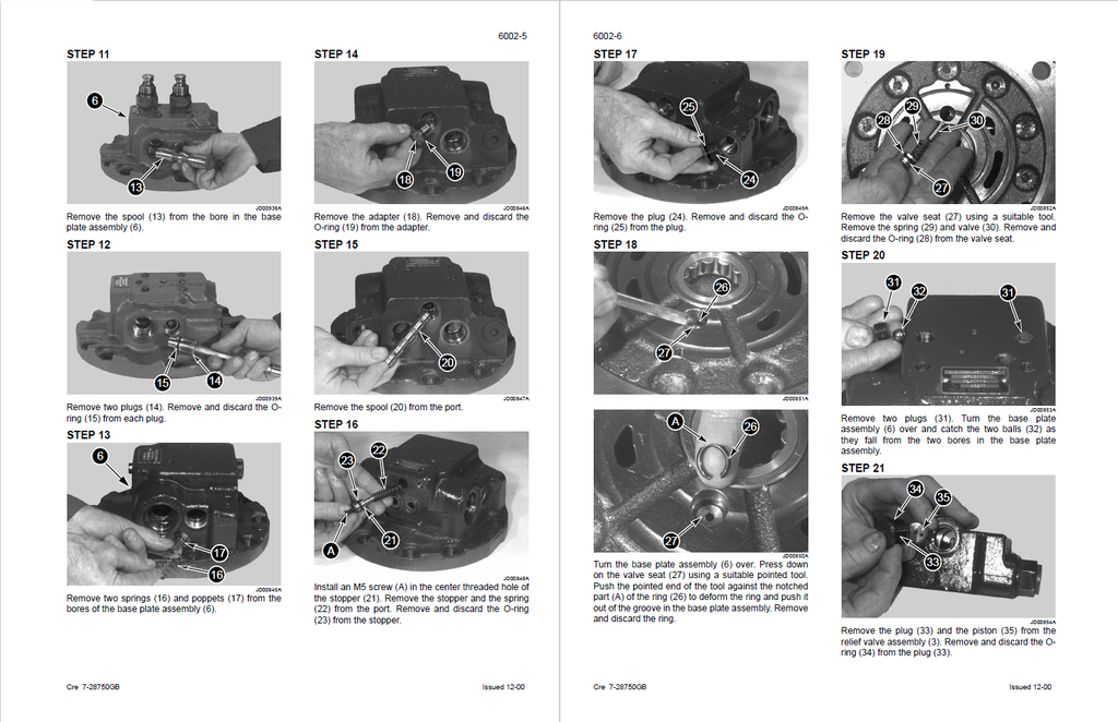
- Main hydraulic pump, disassembly and assembly
- Specifications
- Identifying the ports
- Regulating control
- Disassembly
- Assembly
- Main hydraulic control valve, disassembly and assembly
- Torque setting
- Description
- Dipper load holding block
- Disassembly
- Inspection
- Assembly
- Boom load holding block
- Disassembly
- Inspection
- Assembly
- Non return check valve
- Disassembling the non-return check valve for dipper, bucket and boom 1
- Inspection
- Assembly
- Disassembling the non-return check valves for option, boom 2 and swing
- Inspection
- Assembly
- Disassembling the non-return check valve for RH travel and dipper
- Inspection
- Assembly
- Disassembling the LH travel non-return check valve
- Inspection
- Assembly
- Boom non-return check valve
- Disassembly
- Inspection
- Assembly
- 39 bar supply block
- Disassembly
- Inspection
- Assembly
- Swing priority block
- Disassembly
- Inspection
- Assembly
- Semi-parallel valve block
- Disassembly
- Inspection
- Assembly
- Cancellation valve
- Disassembly
- Inspection
- Assembly
- Free passage locking
- Disassembly
- Inspection
- Assembly
- Safety valve for close bucket, boom lowering, open bucket, boom raising, dipper extend, dipper retract
- Disassembly
- Inspection
- Assembly
- Attachment cylinders, disassembly and assembly
- Special tools
- Cylinders
- Boom cylinder description
- Dipper cylinder description
- Bucket cylinder description
- Disassembly
- Inspection
- Assembly
- Hand control levers, disassembly and assembly
- Specifications
- Control lever
- Description
- Disassembly
- Inspection
- Assembly
- Foot control levers, disassembly and assembly
- Torque settings
- Control pedal
- Description
- Disassembly
- Inspection
- Assembly
- Six-solenoid valves, disassembly and assembly
- Six solenoid valves block
- Identifying the ports and the solenoid valves
- Section
- Disassembly and assembly
- Inspection
- Six solenoid valves block
- Caution valve, disassembly and assembly
- Safety valve
- Hydraulic swivel, disassembly and assembly
- Hydraulic swivel
- Description
- Disassembly
- Assembly
- Hydraulic swivel
- Swing motor, disassembly and assembly
- Specifications
- Torque settings
- Hydraulic swing motor
- Description
- Disassembly
- Inspection
- Assembly
- Hydraulic functions
- Hydraulic functions
- Function list
- Controls in neutral (Pump Uchida) (CX130/CX160)
- Controls in neutral (Pump Kawasaki) (CX130/CX160/CX180)
- High speed travel circuit
- Low speed travel circuit
- Straight line travel circuit
- Swing circuit
- Variable priority valve circuit
- Boom raising circuit
- Boom lowering circuit with load holding valve
- Boom lowering reinjection circuit
- Boom lowering anti-vibration circuit
- Dipper extending circuit
- Dipper retracting circuit
- Dipper retracting reinjection circuit
- Bucket opening circuit
- Bucket closing circuit
- Crusher circuit
- Breaker circuit
- Hydraulic functions
- Depressurising and decontaminating the hydraulic system, use of the vacuum pump and bleeding the components
- Upperstructure
- Quick coupler
- Identification of components
- Description
- Disassembly
- Assembly
- Inspection
- Identification of components
- Upperstructure, turntable and counterweight
- Special torque settings
- Specifications
- Upperstructure
- Inspection
- Removal
- Installation
- Boom, dipper and bucket
- Specifications
- Bucket
- Description
- Removal
- Installation
- Shimming the bucket
- Boom
- Description
- Removal
- Installation
- Seat and seat belt
- Specifications
- Operator’s seat
- Description
- Removal
- Installation
- Cab and cab equipment
- Specifications
- Special torque settings
- Cab
- Removal
- Installation
- Heating block/Air-conditioning block
- Description
- Removal
- Installation
- Air conditioning troubleshooting
- Safety procedures
- Special tools
- Operation
- Refrigerant schematic
- Electrical schematic
- Air conditioning unit disassembly and assembly
- Large format electrical schematic
- Large format hydraulic schematic
- Hydraulic schematic with dozer blade (Huchida pump)
- Hydraulic schematic with dozer blade (Kawasaki pump)
- Quick coupler