

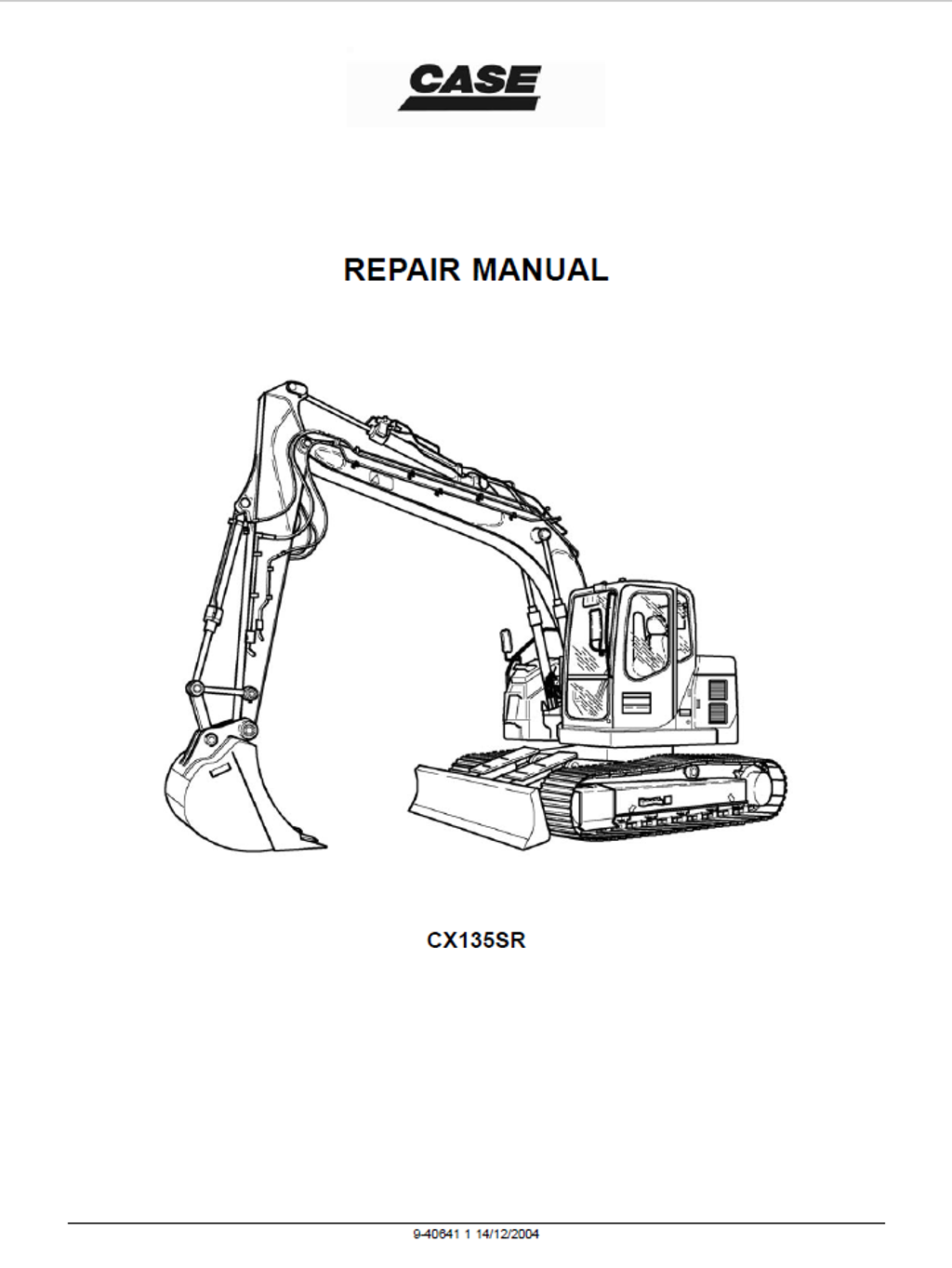
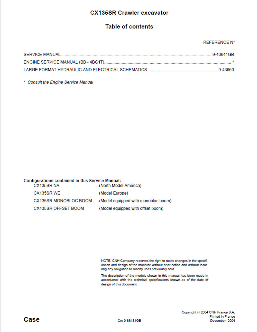
CASE Construction CX135SR Crawler Excavator Service Manual 9-40641NA English
Official Manual Overview
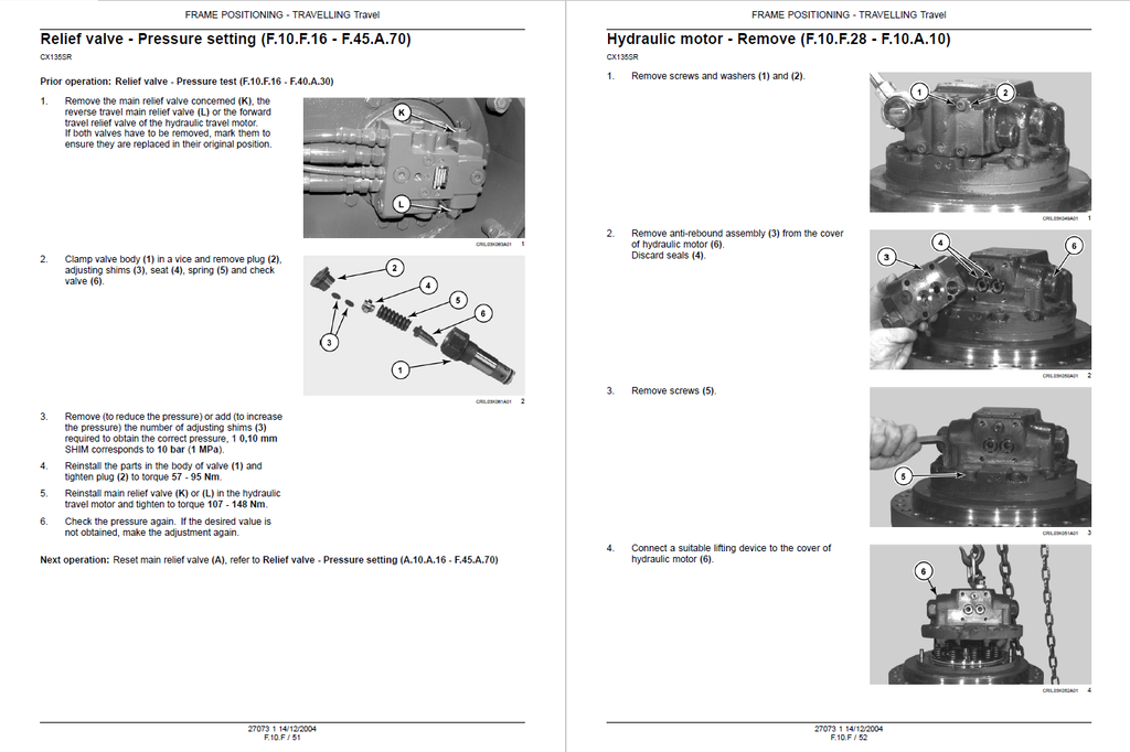
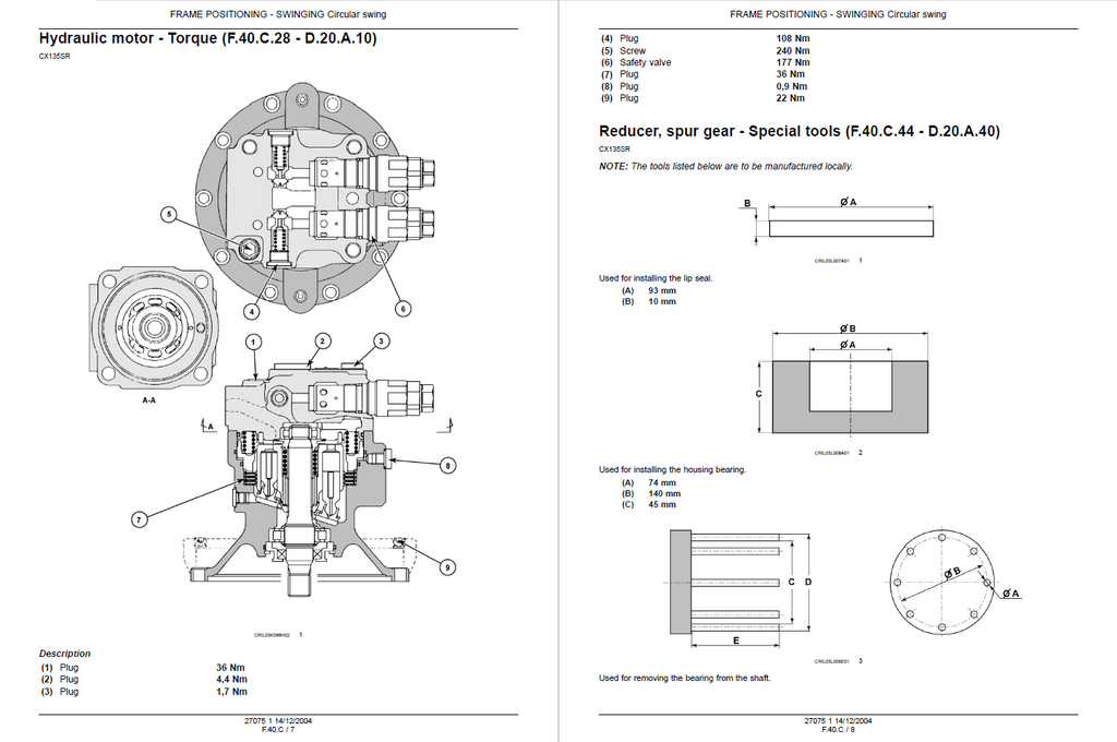
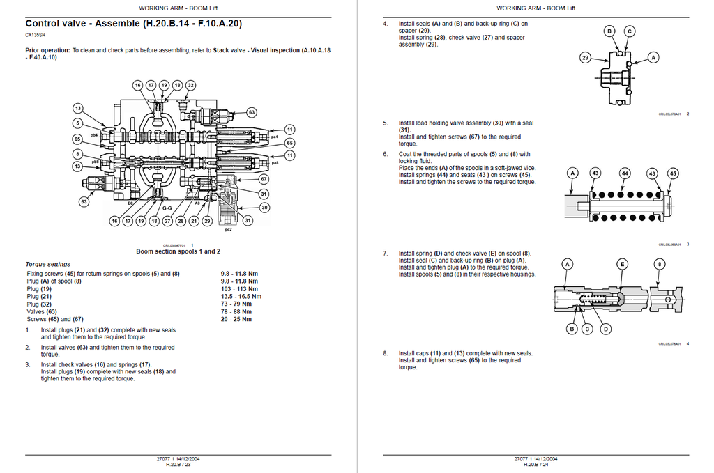
Take absolute command over the versatile zero-tail-swing earthmover with this definitive OEM Service Manual, engineered explicitly for the CASE CX135SR Crawler Excavator. Designed for advanced dealership technicians, this volume delivers uncompromising reconstruction protocols for the entire chassis, undercarriage, and complex hydraulic networks. It provides elite-level calibration metrology for the dual 117.2 L/min variable displacement main pumps and dictates absolutely staggering fastening specifications—including the massive 4780 Nm torque requirement for the dipper cylinder nut and 3180 Nm for the boom cylinder. It extensively covers multiple machine configurations, including both the NA (North America) and WE (Europe) variants, alongside specific structural tear-downs for both Monobloc and Offset Boom architectures. Furthermore, it transforms the cabin into an advanced diagnostic command center with detailed electrical pinout mapping and proportional solenoid troubleshooting. Please note: In strict adherence to CASE's publication strategy, while complete engine removal and external sensor diagnostics are covered, deep internal block teardowns for the Isuzu BB-4BG1T diesel engine are explicitly redirected to a dedicated engine manual.
- Brands: CASE Construction
- Equipment Type: Crawler Excavator
- Manuals Type: Service Manual
- Machine Model: CX135SR (Includes Monobloc & Offset Boom variants)
- Serial Number: N/R
- Region: North America, Europe
- Book Code: 9-40641NA
- Issued: Printed in France, December 2004
- Language: English
- Pages: 820
- File Format: PDF (Searchable)
Core Selling Points
- Surgical Pump Reconstruction Metrology: Stop relying on guesswork and rebuild the primary hydraulic pumps with micrometer-level precision. This literature dictates absolute wear tolerances, mandating a strict 0.067 mm discard limit for piston-to-cylinder bore clearance, a 4.7 mm minimum shoe thickness, and a highly specic 0.1 Ra surface roughness threshold for the cylinder block sliding contact surface after grinding.
- Advanced RED4 & ECM Interception: Eradicate blind electrical diagnostics by tapping directly into the machine's brain. The manual extensively maps out how to utilize the proprietary CAS-30039 and CAS-40041 test connector kits to intercept signals from the RED4 electronic acceleration module. It provides exact pin-by-pin testing paths for TECH 2 (TXD/RXD) communications, emergency stop motors, and proportional solenoid networks.
- Uncompromising Hydraulic Calibration: Master the fluid dynamics required to tune this excavator to absolute factory baselines. Technicians are guided through step-by-step pressure metrology using the Multi-Handy 2051 digital tester and CAS10280 flowmeters. It requires calibrating the negative pressure check to exactly 27 bar (2.7 MPa) and tuning the boom raising secondary relief valve to a strict 391 bar at 20 L/min.
Features & Highlights
- Heavy-Duty Valve Bank Architectures: Prevent catastrophic manifold leaks under extreme mining loads. The documentation outlines rigorous teardown and fastening sequences for the main control valves, demanding immense torque applications such as tightening the spool caps to 271.6 - 277.6 Nm and securing the main body plugs to an exact 213.8 - 217.8 Nm spec.
- Exhaustive Undercarriage Wear Matrices: Stop replacing expensive tracks and rollers based on visual estimates. Mechanics are provided with absolute mathematical wear limits, mandating a hard replacement when the standard 171.5 mm track chain pitch stretches to 166.95 mm, or when the drive sprocket base diameter wears from 530.7 mm down to 524.7 mm.
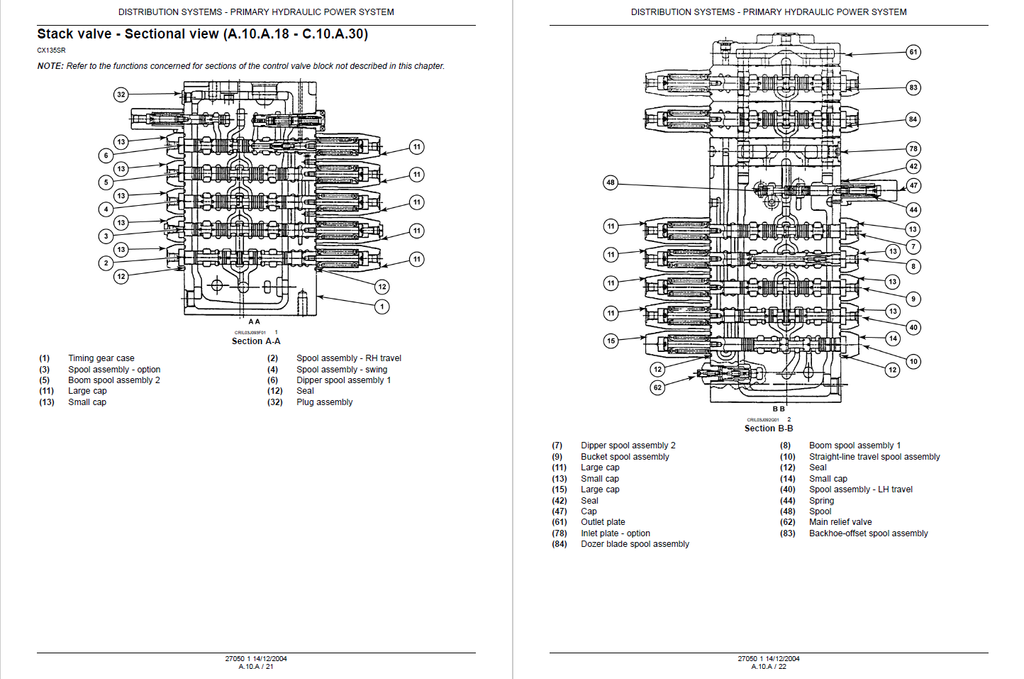
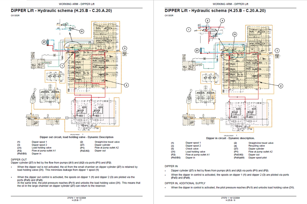
- Dynamic Fluid Logic & Spool Mapping: Navigating the massive control valve banks is made straightforward. The manual features "Dynamic Description" schematics that completely break down the internal spool logic, illustrating exactly how fluid flows from the P2 pump outlet through the Pa7/A7 circuits during bucket opening sequences, simplifying complex flow restrictions.
Problem Solver
- Eradicates Phantom Travel Drift: The step-by-step troubleshooting trees permanently eradicate tracking issues. It instructs technicians to bring hydraulic oil to exactly 50°C on a 30-meter test track, verifying if the pressure difference between P1 and P2 exceeds 30 bar (3 MPa)—instantly pinpointing a failing negative pressure circuit or a defective travel motor displacement spool.
- Cures Intermittent Throttle Failures: Troubleshoot the electronic throttle command definitively. By utilizing the exact timing diagrams and resistance benchmarks, mechanics can isolate elusive power drops to the engine speed detector (B41) or the RED4 limp-home mode, preventing unnecessary and expensive computer replacements.
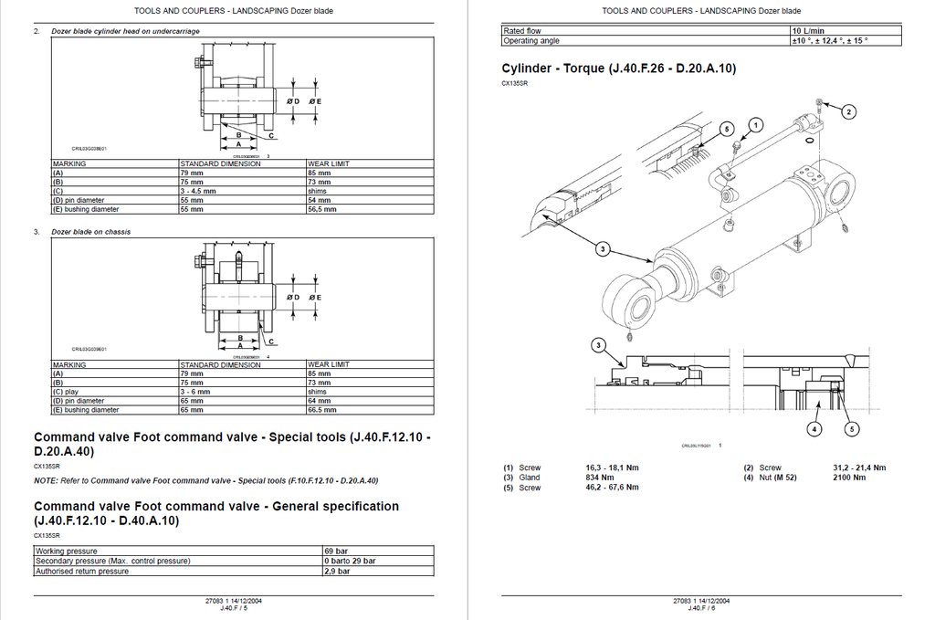
- Prevents Fatal Cylinder Reassembly Mistakes: Improperly secured hydraulic cylinders will blow out under load. This guide safeguards your rebuilds by dictating strict fastening architectures, ensuring components like the offset boom cylinder piston nut are secured to a massive 2620 Nm, while the rod gland is locked in at 834 Nm.
Important Pre-Purchase Advisories
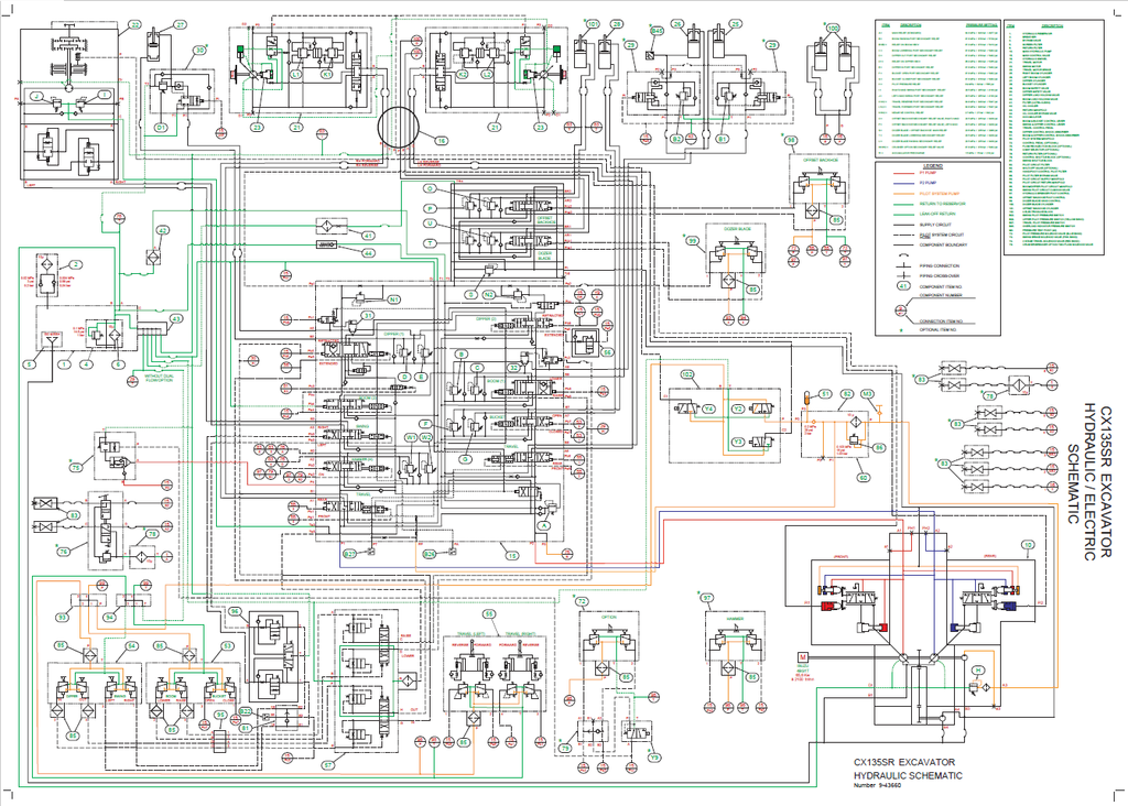
- Complete "Large Format" Schematics Included: Unlike many digital copies that omit physical pocket inserts, this specific manual fully incorporates the original large-format electrical wiring diagrams and complex hydraulic circuit charts (OEM Reference 9-43660) at the end of the file. Technicians receive 100% unbroken end-to-end component routing.
- Dedicated Engine Block Focus: In strict adherence to the manufacturer's publication strategy, this manual exhaustively covers engine removal, installation, electronic acceleration circuits, and external sensor diagnostics. However, deep internal mechanical teardowns of the Isuzu BB-4BG1T diesel engine block are explicitly redirected to the dedicated Engine Service Manual.
Table of Contents
- INTRODUCTION
- Foreword
- Safety rules
- Basic instructions
- Torque
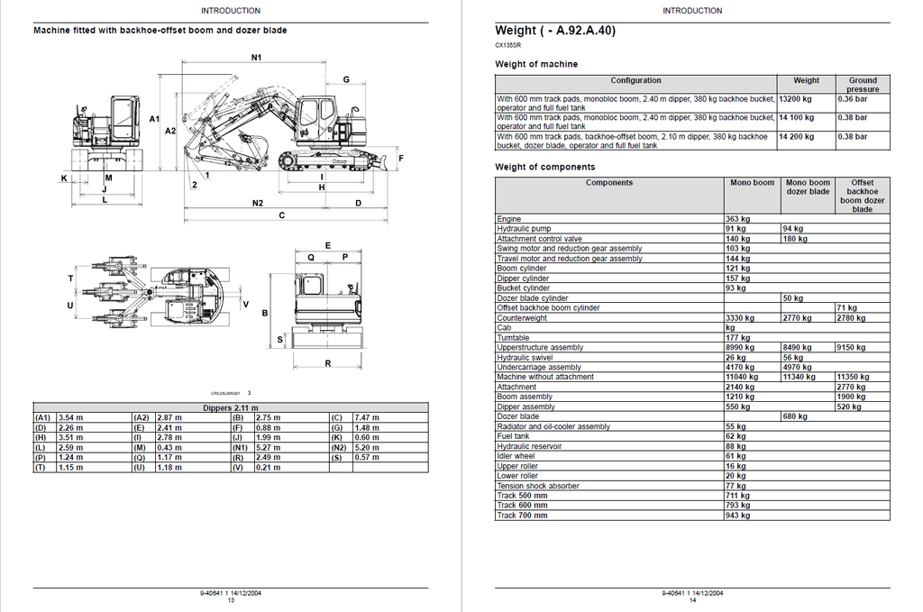
- Dimension
- Weight
- Consumables
- Hydraulic contamination
- Product identification
- DISTRIBUTION SYSTEMS
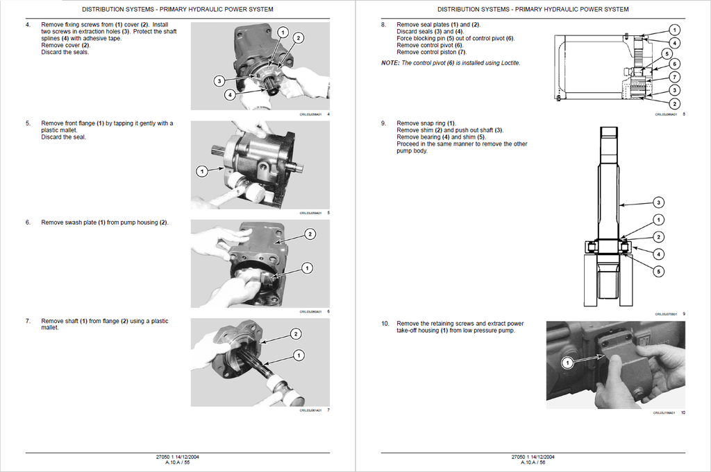
- PRIMARY HYDRAULIC POWER SYSTEM
- TECHNICAL DATA
- General specification
- Special tools
- Seed rates
- Hydraulic pump
- Special tools
- Service limits
- FUNCTIONAL DATA
- Static description
- Dynamic description
- Stack valve
- External view
- Sectional view
- Inlet section - Sectional view
- Outlet section - Sectional view
- Hydraulic pump
- Sectional view
- Exploded view
- Sensing system
- Temperature sensor - Electronic schema
- SERVICE
- Warm up
- Depressurising
- Drain fluid
- Bleed
- Pressure test
- Decontaminating
- Stack valve
- Remove
- Outlet section - Disassemble
- Inlet section - Disassemble
- Visual inspection
- Inlet section - Assemble
- Outlet section - Assemble
- Install
- Relief valve
- Disassemble
- Assemble
- Pressure setting
- Hydraulic pump
- Remove
- Disassemble
- Assemble
- Install
- Bleed
- Pressure test
- Compensator
- Disassemble
- Assemble
- Reservoir
- Remove
- Install
- Oil filter
- Remove
- Install
- Sensing system
- Temperature sensor - Electrical test
- DIAGNOSTIC
- Troubleshooting
- Stack valve
- Troubleshooting
- Relief valve
- Troubleshooting
- TECHNICAL DATA
- SECONDARY HYDRAULIC POWER SYSTEM
- FUNCTIONAL DATA
- Stack valve
- Outlet section - Sectional view
- Inlet section - Sectional view
- Hydraulic pump
- Exploded view
- Sectional view
- Stack valve
- SERVICE
- Stack valve
- Disassemble
- Inlet section - Disassemble
- Inlet section - Assemble
- Assemble
- Relief valve
- Disassemble
- Assemble
- Pressure test
- Pressure setting
- Hydraulic pump
- Remove
- Disassemble
- Assemble
- Install
- Stack valve
- FUNCTIONAL DATA
- HYDRAULIC COMMAND SYSTEM
- SERVICE
- Relief valve
- Pressure test
- Pressure setting
- Hydraulic pump
- Remove
- Install
- Accumulator
- Check
- Relief valve
- DIAGNOSTIC
- Troubleshooting
- SERVICE
- ELECTRICAL POWER SYSTEM
- TECHNICAL DATA
- General specification
- Special tools
- Battery
- General specification
- FUNCTIONAL DATA
- Static description
- Overview
- Fuse and relay box
- Overview
- Fuse - Overview
- Alternator
- Electronic schema
- SERVICE
- Battery
- Visual inspection
- Disconnect
- Remove
- Check
- Charging
- Overhaul
- Install
- Connect
- Battery
- TECHNICAL DATA
- LIGHTING SYSTEM
- FUNCTIONAL DATA
- Front work light
- Electronic schema
- Front work light
- FUNCTIONAL DATA
- PRIMARY HYDRAULIC POWER SYSTEM
- POWER PRODUCTION
- ENGINE
- TECHNICAL DATA
- General specification
- Engine horse power
- FUNCTIONAL DATA
- Electronic schema
- Electronic control
- Electronic schema
- SERVICE
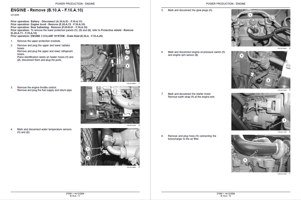
- Remove
- Install
- Sensing system
- Speed sensor - Electrical test
- TECHNICAL DATA
- FUEL AND INJECTION SYSTEM
- FUNCTIONAL DATA
- Throttle command
- Electronic throttle - Functional diagram
- Fuel shut-off
- Electrical shut-off - Electronic schema
- Sensing system
- Level sensor - Electronic schema
- Throttle command
- SERVICE
- Fuel filler aid
- Remove
- Install
- Fuel tank
- Remove
- Install
- Fuel filler aid
- FUNCTIONAL DATA
- AIR INTAKE SYSTEM
- SERVICE
- Air cleaner
- Remove
- Install
- Air cleaner
- SERVICE
- EXHAUST SYSTEM
- SERVICE
- Silencer
- Remove
- Install
- Silencer
- SERVICE
- ENGINE COOLANT SYSTEM
- FUNCTIONAL DATA
- Sensing system
- Coolant temperature - Electronic schema
- Sensing system
- SERVICE
- Drain fluid
- Interior washing
- Filling
- Radiator
- Remove
- Install
- Sensing system
- Coolant temperature - Electrical test
- FUNCTIONAL DATA
- LUBRICATION SYSTEM
- FUNCTIONAL DATA
- Sensing system
- Oil pressure - Electronic schema
- Sensing system
- FUNCTIONAL DATA
- STARTING SYSTEM
- TECHNICAL DATA
- Engine starter
- General specification
- Engine starter
- FUNCTIONAL DATA
- Cold start aid
- Pre-heating - Electronic schema
- Pre-heating - Dynamic description
- Start control
- Start relay - Electronic schema
- Cold start aid
- TECHNICAL DATA
- PTO POWER IN
- SERVICE
- Drive system
- Remove
- Visual inspection
- Install
- Drive system
- SERVICE
- ENGINE
- TRAVELLING
- WHEELS AND TRACKS
- Tracks
- TECHNICAL DATA
- Drive sprocket
- Special tools
- Service limits
- Steel track
- Service limits
- Roller
- Lower roller - Special tools
- Lower roller - Service limits
- Upper roller - Special tools
- Upper roller - Service limits
- Idler wheel
- Special tools
- Service limits
- Drive sprocket
- FUNCTIONAL DATA
- Steel track
- Exploded view
- Track tensioning mechanism
- Shock absorber - Exploded view
- Adjuster-recoil mechanism - Exploded view
- Roller
- Lower roller - Sectional view
- Upper roller - Sectional view
- Steel track
- SERVICE
- Drive sprocket
- Remove
- Install
- Steel track
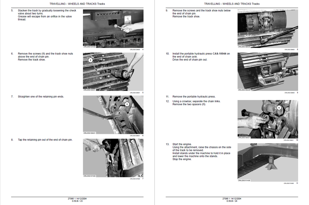
- Remove
- Install
- Chain - Measure
- Rubber track
- Visual inspection
- Remove
- Install
- Track tensioning mechanism
- Tension adjust
- Shock absorber - Remove
- Shock absorber - Disassemble
- Shock absorber - Assemble
- Shock absorber - Install
- Adjuster-recoil mechanism - Remove
- Adjuster-recoil mechanism - Disassemble
- Adjuster-recoil mechanism - Assemble
- Adjuster-recoil mechanism - Install
- Roller
- Leakage test
- Lower roller - Remove
- Lower roller - Disassemble
- Lower roller - Visual inspection
- Lower roller - Assemble
- Lower roller - Install
- Upper roller - Remove
- Upper roller - Disassemble
- Upper roller - Visual inspection
- Upper roller - Assemble
- Upper roller - Install
- Idler wheel
- Disassemble
- Assemble
- Drive sprocket
- TECHNICAL DATA
- Tracks
- WHEELS AND TRACKS
- BODY AND STRUCTURE
- SHIELD
- SERVICE
- Side shield
- Remove
- Upper shield
- Remove
- Engine hood
- Remove
- Protective shield
- Remove
- Side shield
- SERVICE
- USER CONTROLS AND SEAT
- FUNCTIONAL DATA
- Instrument panel
- Detailed view
- Instrument panel
- FUNCTIONAL DATA
- USER PLATFORM
- FUNCTIONAL DATA
- Wiper system
- Electronic schema
- Windscreen washer system
- Electronic schema
- Wiper system
- FUNCTIONAL DATA
- ENVIRONMENT CONTROL
- Heating, ventilation and air-conditioning
- TECHNICAL DATA
- Special tools
- FUNCTIONAL DATA
- Dynamic description
- Command
- Overview
- Electronic HVAC control
- Electrical schema
- SERVICE
- Evacuate
- Charging
- Disassemble
- Compressor
- Remove
- Install
- Condenser
- Remove
- Install
- Receiver/drier
- Remove
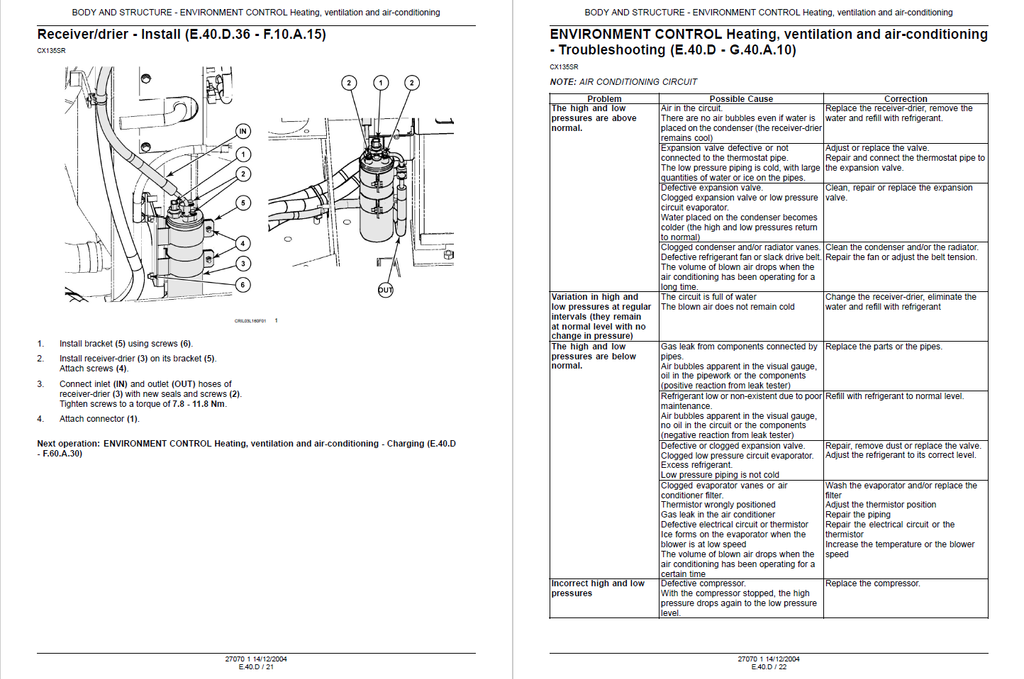
- Install
- DIAGNOSTIC
- Troubleshooting
- Compressor
- Magnetic clutch - Troubleshooting
- Ventilation system
- Troubleshooting
- TECHNICAL DATA
- Heating, ventilation and air-conditioning
- SAFETY SECURITY ACCESSORIES
- Safety
- FUNCTIONAL DATA
- Hydraulic lock-out
- Electrical schema
- Electrovalve - External view
- Electrovalve - Sectional view
- Hydraulic lock-out
- SERVICE
- Hydraulic lock-out
- Electrovalve - Electrical test
- Electrovalve - Remove
- Electrovalve - Disassemble
- Electrovalve - Visual inspection
- Electrovalve - Assemble
- Electrovalve - Install
- Hydraulic lock-out
- FUNCTIONAL DATA
- Safety
- SHIELD
- FRAME POSITIONING
- TRAVELLING
- Travel
- TECHNICAL DATA
- Command valve
- Foot command valve - Special tools
- Foot command valve - General specification
- Hydraulic motor
- Torque
- Reducer, spur gear
- Special tools
- Command valve
- FUNCTIONAL DATA
- Electronic schema
- Hydraulic schema
- Command valve
- Foot command valve - Sectional view
- Control valve
- Sectional view
- Hydraulic motor
- Exploded view
- Sectional view
- Reducer, spur gear
- Exploded view
- Sectional view
- Sensing system
- Alarm - Electronic schema
- SERVICE
- Command valve
- Foot command valve - Remove
- Foot command valve - Disassemble
- Foot command valve - Visual inspection
- Foot command valve - Assemble
- Foot command valve - Install
- Speed selection valve - Overhaul
- Speed selection valve - Electrical test
- Control valve
- Disassemble
- Assemble
- Relief valve
- Pressure test
- Pressure setting
- Hydraulic motor
- Remove
- Disassemble
- Check
- Assemble
- Install
- Leakage test
- Reducer, spur gear
- Remove
- Disassemble
- Visual inspection
- Measure
- Bearing - Preload
- Assemble
- Install
- Command valve
- DIAGNOSTIC
- Troubleshooting
- Command valve
- Foot command valve - Troubleshooting
- TECHNICAL DATA
- Travel
- STABILISING
- Ballasting
- SERVICE
- Rear ballasting
- Remove
- Rear ballasting
- SERVICE
- Ballasting
- SWINGING
- Circular swing
- TECHNICAL DATA
- Command valve
- Hand command valve - Torque
- Hydraulic motor
- Service limits
- Special tools
- Torque
- Reducer, spur gear
- Special tools
- Swivel
- General specification
- Command valve
- FUNCTIONAL DATA
- Hydraulic schema
- Command valve
- Hand command valve - Sectional view
- Control valve
- Sectional view
- Hydraulic motor
- Sectional view
- Reducer, spur gear
- Sectional view
- Hydraulic brake
- Electronic schema
- Swivel
- Exploded view
- SERVICE
- Command valve
- Hand command valve - Remove
- Hand command valve - Disassemble
- Hand command valve - Cleaning
- Hand command valve - Visual inspection
- Hand command valve - Assemble
- Hand command valve - Install
- Control valve
- Disassemble
- Assemble
- Relief valve
- Pressure test
- Pressure setting
- Hydraulic motor
- Leakage test
- Remove
- Disassemble
- Visual inspection
- Assemble
- Install
- Bleed
- Reducer, spur gear
- Remove
- Disassemble
- Visual inspection
- Assemble
- Install
- Bearing and ring gear
- Remove
- Check
- Install
- Hydraulic brake
- Pressure test
- Electrovalve - Electrical test
- Swivel
- Remove
- Disassemble
- Cleaning
- Assemble
- Install
- Command valve
- TECHNICAL DATA
- Circular swing
- TRAVELLING
- WORKING ARM
- BOOM
- Lift
- TECHNICAL DATA
- Service limits
- Command valve
- Hand control valve - Torque
- Cylinder
- Torque
- Special tools
- FUNCTIONAL DATA
- Hydraulic schema
- Command valve
- Hand control valve - Sectional view
- Control valve
- Sectional view
- Cylinder
- Sectional view
- Arm
- Exploded view
- Sensing system
- Electronic schema
- SERVICE
- Command valve
- Hand control valve - Overhaul
- Cushion valve - Remove
- Cushion valve - Disassemble
- Cushion valve - Assemble
- Cushion valve - Install
- Control valve
- Disassemble
- Assemble
- Safety valve
- Remove
- Disassemble
- Assemble
- Install
- Pressure setting
- Relief valve
- Disassemble
- Assemble
- Pressure test
- Pressure setting
- Load holding valve
- Disassemble
- Assemble
- Arm
- Remove
- Install
- Cylinder
- Remove
- Disassemble
- Visual inspection
- Assemble
- Install
- Command valve
- TECHNICAL DATA
- Swing
- TECHNICAL DATA
- Cylinder
- Torque
- Boom
- Service limits
- Cylinder
- FUNCTIONAL DATA
- Hydraulic schema
- Control valve
- Sectional view
- Cylinder
- Sectional view
- SERVICE
- Command valve
- Foot command valve - Remove
- Foot command valve - Install
- Foot command valve - Overhaul
- Control valve
- Disassemble
- Assemble
- Relief valve
- Overhaul
- Pressure test
- Pressure setting
- Cylinder
- Remove
- Disassemble
- Assemble
- Install
- Command valve
- TECHNICAL DATA
- Lift
- DIPPER
- Lift
- TECHNICAL DATA
- Service limits
- Command valve
- Hand control valve - Torque
- Cylinder
- Torque
- FUNCTIONAL DATA
- Hydraulic schema
- Command valve
- Hand control valve - Sectional view
- Control valve
- Sectional view
- Cylinder
- Sectional view
- SERVICE
- Command valve
- Hand control valve - Overhaul
- Cushion valve - Remove
- Cushion valve - Disassemble
- Cushion valve - Assemble
- Cushion valve - Install
- Control valve
- Disassemble
- Assemble
- Safety valve
- Remove
- Disassemble
- Assemble
- Install
- Pressure setting
- Relief valve
- Overhaul
- Pressure test
- Pressure setting
- Load holding valve
- Disassemble
- Assemble
- Cylinder
- Remove
- Disassemble
- Assemble
- Install
- Arm
- Remove
- Install
- Command valve
- TECHNICAL DATA
- Lift
- ARM TOOL ATTACHMENT
- Tilt
- TECHNICAL DATA
- Service limits
- Command valve
- Hand control valve - Torque
- Cylinder
- Torque
- FUNCTIONAL DATA
- Hydraulic schema
- Command valve
- Hand control valve - Sectional view
- Control valve
- Sectional view
- Cylinder
- Sectional view
- SERVICE
- Command valve
- Hand control valve - Overhaul
- Control valve
- Disassemble
- Assemble
- Relief valve
- Overhaul
- Pressure test
- Pressure setting
- Cylinder
- Remove
- Disassemble
- Assemble
- Install
- Arm
- Remove
- Install
- Command valve
- TECHNICAL DATA
- Tilt
- BOOM
- TOOLS AND COUPLERS
- DIGGING
- Hammer
- FUNCTIONAL DATA
- Hydraulic schema
- Control valve
- Sectional view
- SERVICE
- Command valve
- Foot command valve - Overhaul
- Control valve
- Disassemble
- Assemble
- Command valve
- FUNCTIONAL DATA
- Hammer
- LANDSCAPING
- Dozer blade
- TECHNICAL DATA
- Service limits
- Command valve
- Foot command valve - Special tools
- Foot command valve - General specification
- Cylinder
- Torque
- FUNCTIONAL DATA
- Hydraulic schema
- Control valve
- Sectional view
- Cylinder
- Sectional view
- SERVICE
- Command valve
- Foot command valve - Remove
- Foot command valve - Disassemble
- Foot command valve - Visual inspection
- Foot command valve - Assemble
- Foot command valve - Install
- Control valve
- Disassemble
- Assemble
- Relief valve
- Overhaul
- Pressure test
- Pressure setting
- Cylinder
- Remove
- Disassemble
- Assemble
- Install
- Command valve
- DIAGNOSTIC
- Command valve
- Foot command valve - Troubleshooting
- Command valve
- TECHNICAL DATA
- Dozer blade
- DIGGING
- Large format hydraulic and electrical schematics