

CASE Construction CX16B, CX18B Mini Excavator Service Manual 9-88670 English
Official Manual Overview
Command the intricate hydraulics and tight-quarter performance of the CASE CX16B and CX18B Mini Excavators with this uncompromising OEM Service Manual. Far exceeding basic maintenance charts, this master reference provides dealership-level technicians with complete teardown and reconstruction metrology for both the standard fixed-frame and the advanced adjustable crawler width undercarriage configurations. It enforces strict diagnostic baselines for the equipped YANMAR 3TNE74 1.006L diesel engine and demands absolute mathematical precision when calibrating the variable displacement axial-piston hydraulic pumps, dictating an exact 210 kgf/cm² (2990 psi) main relief threshold and strict 280 kgf/cm² (3980 psi) overload limits for the boom and dozer circuits. From rebuilding the two-speed planetary travel motors to mapping the complex internal logic of the 10-spool multiple control valves, this guide delivers the exact factory-grade parameters required to eradicate pressure loss, diagnose CAN/electrical harnesses, and restore flawless trenching precision.
- Brands: CASE Construction
- Equipment Type: Mini Excavator
- Manuals Type: Service Manual
- Machine Model: CX16B, CX18B
- Serial Number: N/R
- Region: N/R
- Book Code: 9-88670
- Issued: Printed in France, January 2004
- Language: English
- Pages: 636
- File Format: PDF (Searchable)
Core Selling Points
- Surgical Hydraulic Core Metrology: Rebuild the machine's fluid power heart with absolute factory precision. This manual dictates the exact internal teardown sequences for the main hydraulic pump and 10-spool control valves, enforcing critical torque specifications such as 103.9 ± 10.4 Nm for the pump’s V2 capscrews and a delicate 3.92 to 4.9 Nm specification for the internal spools, preventing catastrophic casing warpage and internal hemorrhaging.
- Complete Yanmar Engine Reconstruction: Unlike standard chassis-only manuals, this volume features a massive dedicated section for the complete mechanical overhaul of the equipped Yanmar TNE series diesel engines. It demands absolute mathematical certainty from machinists, establishing a strict 0.090 to 0.271 mm tolerance for the crankshaft thrust gap and enforcing a 0.610 to 0.778 mm baseline for piston top clearances to restore peak compression.
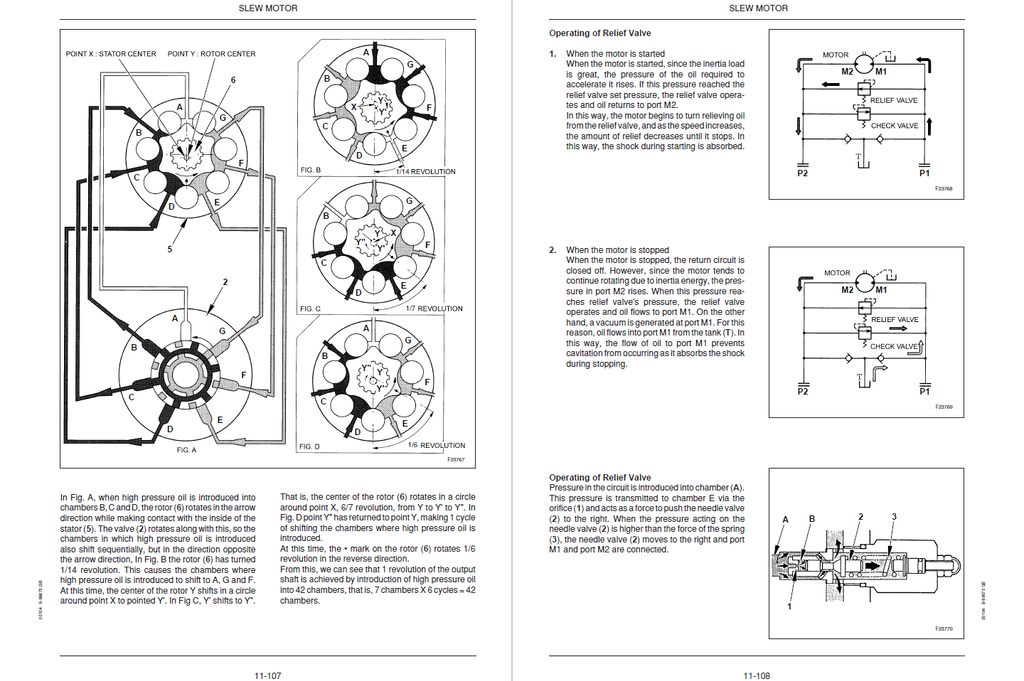
- Planetary & Slew Motor Overhauls: Stop throwing away expensive travel and swing drives. The literature guides technicians through the microscopic breakdown of the reduction gears and hydraulic motors, demanding an exact 42 Nm fastening torque when mating the slew motor to the gearbox housing, while detailing the exact extraction sequence for the roller gerotors, distributor plates, and brake disc packs.
Features & Highlights
- Dealership-Tier Pressure Calibration: Equip your workshop to tune the hydraulic architecture using specified 500 kgf/cm² (7110 psi) gauge kits. Mechanics are explicitly instructed to calibrate the P1 and P2 main relief circuits to a precise 210 kgf/cm² (2990 psi) standard, and strictly adjust the boom and dozer port relief valves to an aggressive 280 kgf/cm² (3980 psi) to guarantee maximum trenching breakout force.
- Deep-Level Electrical Interrogation: Bypass parts-cannon diagnostics with comprehensive wiring matrices. The guide completely maps out the Sequence Box (E-14) and relay networks, providing specific multimeter benchmarks—such as verifying exactly 12V across the yellow and black wires of the CN-109F connector to instantly isolate a failed two-speed travel solenoid from a severed chassis harness.
- Sequential Symptom Flowcharts: Navigate elusive operational failures with highly logical "YES/NO" diagnostic trees. Troubleshoot "Incapable of Travel" errors by sequentially checking the 35 kgf/cm² (500 psi) pilot pump secondary pressure, verifying the No. 2 fuse integrity, and measuring the exact liter-per-minute internal drain rate of the travel motors to definitively condemn a scored spool or a blown seal.
Problem Solver
- Cures Phantom Starting & Smoking Issues: Troubleshoot Yanmar injection failures scientifically. The text provides exact mathematical formulas for shimming the injection nozzles, explicitly stating that increasing the pressure adjusting shim by exactly 0.1 mm will raise the indirect injection pressure by 7 to 10 kgf/cm², instantly curing black exhaust smoke and erratic idling.
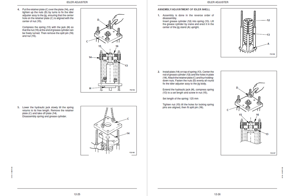
- Resolves Destructive Track Throwing: Recover from severe undercarriage degradation on both the fixed-frame and adjustable crawler width configurations. The manual establishes strict wear limits for the lower rollers and idlers, while mandating the crawler tension droop be precisely adjusted to a 35 to 45 mm window using the grease cylinder, ensuring flawless stability on steep grades.
- Eradicates Unexplained Overheating: Eliminate hidden thermal events that threaten the engine block. Exhaustive procedures guide builders through testing the wax-pellet thermostat by submerging it in heated fluid, requiring physical verification that the valve initiates opening precisely between 69.5°C and 72.5°C and achieves an 8.0 mm minimum lift at 85°C.
Important Pre-Purchase Advisories
- Comprehensive Chassis & Engine Volume: This specific OEM manual serves as the ultimate all-in-one technical blueprint. It exceptionally combines the exhaustive chassis systems (hydraulics, cab electronics, adjustable undercarriage) with deep, micrometer-level internal rebuild data for the Yanmar diesel engine series, eliminating the need to purchase a separate engine overhaul book.
Table of Contents
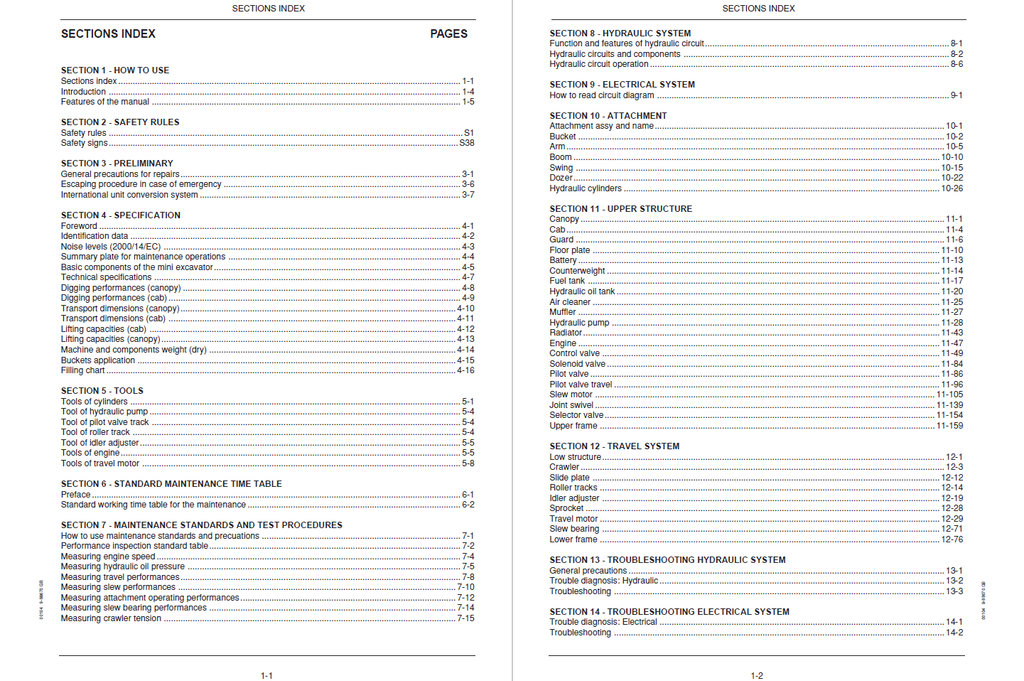
- HOW TO USE
- Sections index
- Introduction
- Manual handling
- Symbols and indications
- Features of the manual
- Manual composition
- Brief information for manual consultation
- SAFETY RULES
- Safety rules
- Safety signs
- PRELIMINARY
- General precautions for repairs
- Escaping procedure in case of emergency
- International unit conversion system
- SPECIFICATION
- Foreword
- Identification data
- Noise levels (2000/14/EC)
- Summary plate for maintenance operations
- Basic components of the mini excavator
- Fixed crawler frame version
- Adjustable crawler frame width version
- Technical specifications
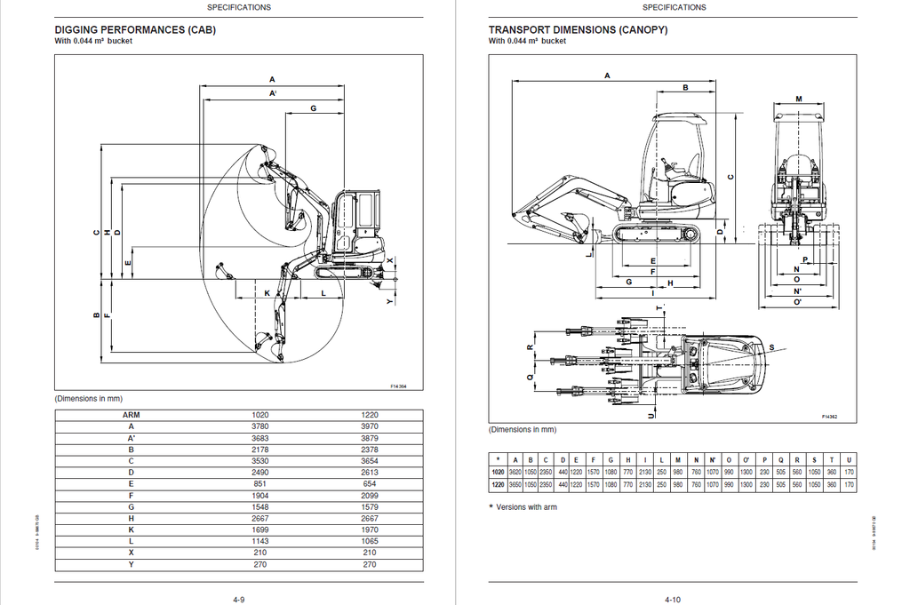
- Digging performances (canopy)
- Digging performances (cab)
- Transport dimensions (canopy)
- Transport dimensions (cab)
- Lifting capacities (cab)
- Lifting capacities (canopy)
- Machine and components weight (dry)
- Buckets application
- Filling chart
- SPECIAL TOOLS
- Tools of cylinders
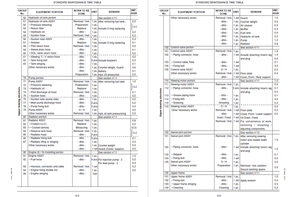
- STANDARD MAINTENANCE TIME TABLE
- Preface
- Standard working time table for the maintenance
- Attachment
- Floor assy, Canopy (Cab) & Guard
- Upper slewing structure
- Travel system
- MAINTENANCE STANDARDS AND TEST PROCEDURES
- How to use maintenance standards and precuations
- Performance inspection standard table
- Measuring engine speed
- Measuring hydraulic oil pressure
- Measuring travel performances
- Measuring slew performances
- Measuring attachment operating performances
- Measuring slew bearing performances
- Measuring crawler tension
- HYDRAULIC SYSTEM
- Function and features of hydraulic circuit
- Hydraulic circuits and components
- Rigid crawler frame
- Adjustable crawler frame width
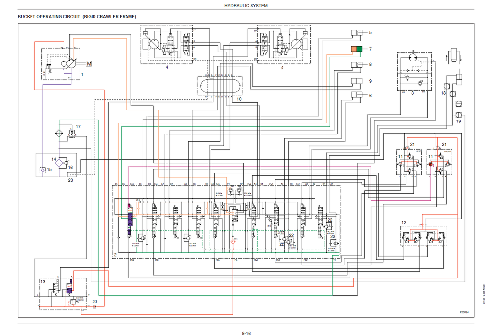
- Hydraulic circuit operation
- Neutral circuit
- Travel operating circuit
- Slew operating circuit
- Bucket operating circuit
- Boom operating circuit
- Arm operating circuit
- Swing operating circuit
- Dozer operating circuit -adjustable crawler frame width operating circuit
- Travel / dozer combined operating circuit
- Nibbler / breaker operating circuit
- ELECTRICAL SYSTEM
- How to read circuit diagram
- Electrical system reading key
- Relay box
- Harness assy, upp
- Harness engine
- Consolle box + relay unit
- Harness assy, boom
- Main harness
- Engine harness
- Key switch harness
- Frame ground cable
- Light harness
- Battery cable (+)
- Battery cable (-)
- How to read circuit diagram
- ATTACHMENT
- Attachment assy and name
- Bucket
- Buckets for digging
- Ditch cleaning bucket
- Arm
- Boom
- Swing
- Dozer
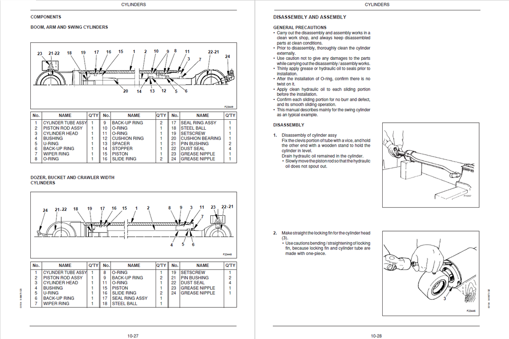
- Hydraulic cylinders
- Maintenance standards
- Troubleshooting
- UPPER STRUCTURE
- Canopy
- Cab
- Disassembly and assembly
- Guard
- Disassembly and assembly
- Floor plate
- Disassembly and assembly
- Battery
- Counterweight
- Fuel tank
- Hydraulic oil tank
- Air cleaner
- Muffler
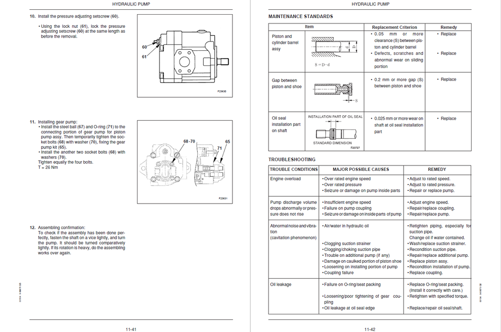
- Hydraulic pump
- Specifications
- Components
- Operation
- Disassembly and asselbly
- Maintenance standards
- Troubleshooting
- Radiator
- Engine
- Control valve
- General view and hydraulic ports no.
- Specifications
- Costruction
- Hydraulic circuit
- Components
- Explanation of operation
- Disassembly and assembly
- Maintenance standard
- Troubleshooting
- Solenoid valve
- Pilot valve
- Pilot valve travel
- Specifications
- Caracteristic
- Performance
- Components
- Operation
- Disassembly and assembly
- Troubleshooting
- Slew motor
- Operation
- Slew motor lubrication
- Troubleshooting
- Joint swivel
- Fixed crawler frame version
- Adjustable crawler frame width version
- Components
- Maintenance standards
- Troubleshooting
- Selector valve
- Adjustable crawler frame width version only
- Specifications
- Operation
- Construction
- Disassembly and assembly
- Troubleshooting
- Upper frame
- TRAVEL SYSTEM
- Low structure
- Rigid crawler frame
- Adjustable crawler frame width
- Crawler
- Rubber crawler
- Iron crawler
- Maintenance standars
- Slide plate
- Roller tracks
- Idler adjuster
- Sprocket
- Travel motor
- Slew bearing
- Lower frame
- (Adjustable crawler frame width)
- Low structure
- TROUBLESHOOTING HYDRAULIC SYSTEM
- General precautions
- Trouble diagnosis: Hydraulic
- Troubleshooting
- TROUBLESHOOTING ELECTRICAL SYSTEM
- Trouble diagnosis: Electrical
- Troubleshooting
- TROUBLESHOOTING ENGINE
- Trouble diagnosis: Engine
- Troubleshooting
- Starter not rotate
- Starter rotates but hard to start
- Rotation trouble
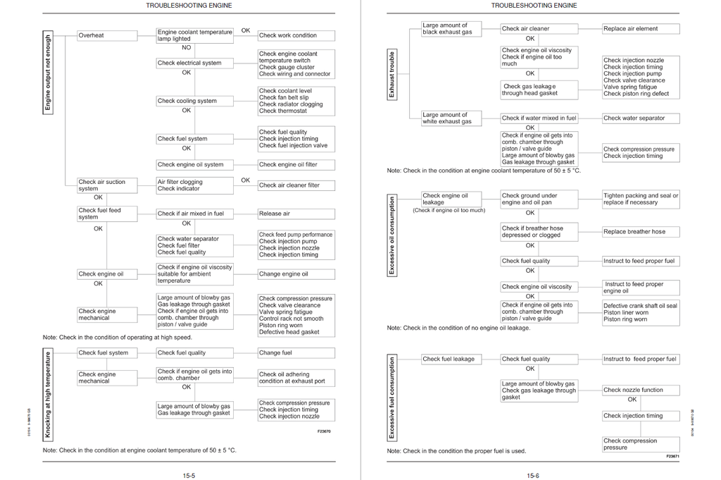
- Engine output not enough
- Knocking at high temperature
- Exhaust trouble
- Excessive oil consumption
- Excessive fuel consumption
- Engine not stop when key turned OFF
- ENGINE
- Specifications and Performance
- 2TNE68
- 3TNE68
- 3TNE74
- 3TNE78A
- 3TNE82A
- 3TNE82
- 3TNE84
- 3TNE88
- 4TNE82
- 4TNE84
- 4TNE88
- 3TNE84T
- 4TNE84T
- Cross Sectional Views
- Special Swirl Precombustion Chamber System
- Direct Injection System
- Cooling water, lubricating oil and fuel oil
- Cooling water
- Lubricating oil
- Fuel oil
- Troubleshooting
- Trouble causes and remedies
- Trouble diagnosis through measurement of compression pressure
- Measuring instruments
- Measurement, inspection and adjustment
- Adjustment the valve head clearance
- Checking the v-belt tension
- Measuring and checking the injection pressure and spray patterns of the fuel injection valve
- Checking and adjustament the fuel injection timing
- Adjustament the no-load maximum (or minimum) revolutions
- Checking the cooling water system and radiator for water leakage
- Checking the battery
- Checking the sensors
- Checking the oil cooler
- Checking the piston cooling nozzle
- Measuring Procedure, Service Data and Corrective Action
- Cylinder head
- Cylinder block
- Valve rocker arm
- Piston and piston ring
- Connecting rod
- Camshaft
- Crankshaft
- Gears
- Disassembly and reassembly
- Disassembly
- Precautions before and during reassembly
- Service data
- Cylinder head
- Cylinder block
- Valve rocker arm
- Piston
- Piston ring
- Connecting rod
- Camshaft
- Crankshaft
- Side gap and backlash
- Others
- Tightening torque
- Fuel injection pump for indirect injection system
- Fuel Injection Pump for Direct Injection System
- Exploded view (YPES type)
- Special service tools for disassembly and reassembly
- Disassembly
- Inspection
- Reassembly
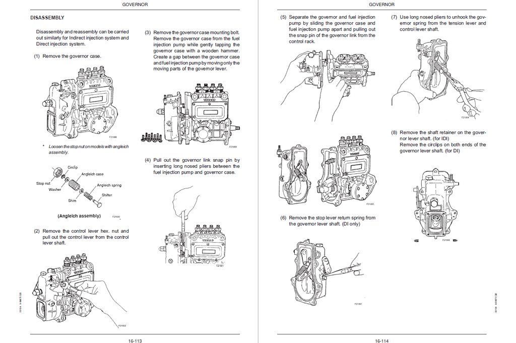
- Governor
- Turbocharger
- Service information for CARB ULG regulation
- Specifications and Performance