

CASE Construction CX210, CX230, CX240 Crawler Excavator Service Manual 9-93610 English
Official Manual Overview
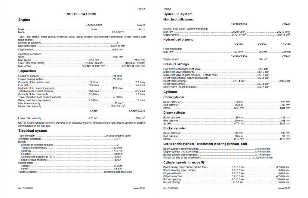
Dominate your heavy-duty repair schedule with this uncompromising OEM Service Manual explicitly focused on the CASE CX210, CX230, and CX240 Crawler Excavators. Engineered for advanced fluid-power and powertrain technicians, this master blueprint delves into the unique structural and hydraulic variations across these three specific weight classes—differentiating the 2x201 L/min Kawasaki twin-pump output of the CX210/CX230 from the massive 2x212 L/min displacement and 5100 kg counterweight architecture of the CX240. It completely decodes the machine's onboard computer interface, granting mechanics direct access to hidden CHK and DIAG monitoring screens for real-time CAN-Bus evaluation of the Isuzu BB-6BG1T engine's electronic governor and proportional circuitry. Expect absolute micrometer-level undercarriage wear limits and unrelenting fastening metrics, including the staggering 1333–1549 Nm torque required for the CX240's M30 counterweight bolts, alongside exact 373 bar (37.3 MPa) 2-stage main relief valve calibrations.
Important Notice: While this volume provides exhaustive diagnostic, chassis, and electro-hydraulic schematics, it explicitly directs technicians to consult the independent Isuzu Engine Service Manual for deep internal block reconstructions of the BB-6BG1T powerplants.
- Brands: CASE Construction
- Equipment Type: Crawler Excavator
- Manuals Type: Service Manual
- Machine Model: CX210, CX230, CX240
- Serial Number: N/R
- Region: N/R
- Book Code: 9-93610
- Issued: Printed in France - May 2005
- Language: English
- Pages: 648
- File Format: PDF (Searchable)
Core Selling Points
- Sub-Millimeter Swing Motor Metrology: Eliminate diagnostic guesswork during complex swing drive overhauls. This master manual dictates absolute factory wear limits for internal rotary components, instructing technicians to condemn the hydraulic motor immediately if the clearance between the piston and barrel bore exceeds the strict 0.052 mm tolerance, or if the sliding shoe thickness wears down past 5.3 mm.
- Colossal Actuator Fastening Specifications: Rebuild heavy-duty lift cylinders with uncompromising structural integrity. This blueprint provides the exact fastening sequences for the attachment cylinders using the OEM 9797 hydraulic repair bench. It mandates massive torque applications, enforcing a 4820 Nm lock on the CX210/CX230 boom piston nut, and an immense 5500 Nm torque requirement specifically for the heavier CX240.
- Deep-Level Kawasaki Pump Reconstruction: Execute dealership-level teardowns on the primary hydraulic pumps and main control valves. The literature details every step of the internal breakdown, strictly regulating chassis and fluid-power hardware mating—such as applying exactly 431 Nm to the pump body retaining screws and 117.7 Nm to the swing motor reduction gear bolts to ensure a leak-free, high-pressure seal.
Features & Highlights
- Live-Parameter Controller Diagnostics: Take absolute command of the main and engine electronic control modules. The text reveals the exact keypad sequences required to access the monitor's hidden diagnostic matrix (including the CHK, DIAG, and HR history screens). This empowers mechanics to verify live electronic signals, such as confirming the CX240's main pump proportional solenoid is receiving exactly 424 mA at a 2000 rpm engine speed.
- Advanced Electro-Hydraulic Benchmarking: Calibrate the fluid power system scientifically. Armed with the CAS 30038 test kit and flowmeters, technicians are guided to adjust the secondary relief valves and verify that the automatic power boost circuit aggressively steps up the main working pressure from 34.3 MPa to exactly 37.3 MPa (5410 psi) on the CX210-CX240 class machines.
- Pin-by-Pin Harness Topologies: Navigate the excavator's complex nervous system with crystal-clear routing logic. The documentation details the use of the proprietary CAS-30039 service connector kit and CAS-1559 multimeter to trace voltage drops across specific color-coded harnesses—such as tracking the LgY (Light Green/Yellow) wire for the engine oil pressure switch or isolating the CAN-Bus communication circuit.
Problem Solver
- Decoding Phantom Dashboard Alarms: Eradicate elusive warning messages like "ELEC. PROBLEM" or "OVER HEAT". The troubleshooting flowcharts teach you how to retrieve specific digital fault codes (such as E0015 for the coolant temperature sensor, E0031 for the linear motor control circuit, or M0020 for the hydraulic oil temperature sensor), transforming erratic electronic failures into calculated, component-level repairs.
- Isolating Attachment Power Loss: Systematically defeat sluggish boom lift or dipper retract speeds. By tapping into the designated test ports (M3), mechanics can verify if the pilot circuit is holding a steady 28 bar (405 psi) baseline, definitively proving whether the issue is a failing gear pump or a blown internal O-ring in the 6-solenoid valve bank before ripping into the main control valve.
- Defeating Hydrostatic Travel Degradation: Stop wasting money blindly replacing entire final drives. The manual empowers you to perform dynamic travel bypass checking and trace electrical continuity through the 2-stage travel solenoid valve (identified by the red band), diagnosing exactly whether a slow track is caused by a failing S2 travel mode switch or internal mechanical leakage inside the reduction gear.
Important Pre-Purchase Advisories
- Engine Overhaul Exclusions: While this Service Manual extensively covers engine removal, installation, cooling, fuel systems, and electronic governor diagnostics, it explicitly directs technicians to consult the independent "Isuzu Engine Service Manual" for deep internal engine block teardowns (such as crankshaft and piston replacement) for the BB-6BG1T powerplants.
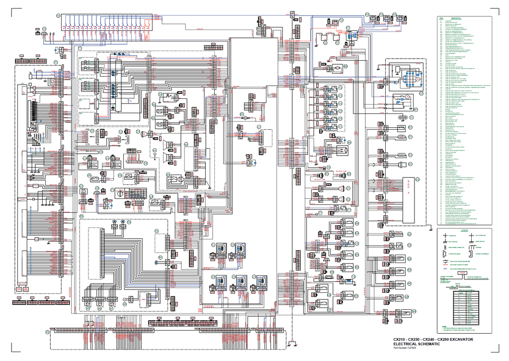
- Fold-out Schematics Location: Please note that the highly detailed, large-format hydraulic and electrical schematics (originally designated as Reference No. 7-27623) are physically consolidated in the "Pocket" section at the end of the publication.
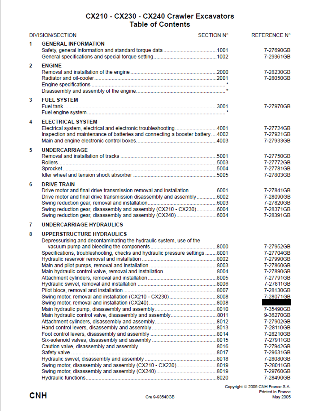
Table of Contents
- GENERAL INFORMATION
- SAFETY
- STANDARD TORQUE DATA FOR CAP SCREWS AND NUTS
- ELECTRICAL AND ELECTRONIC CIRCUIT AND TROUBLESHOOTING
- SPECIFICATIONS
- SPECIAL TOOLS
- LOCATION OF COMPONENTS
- Engine checks
- Work mode selection
- H/S/L mode checking
- Auto mode checking
- Acceleration checking
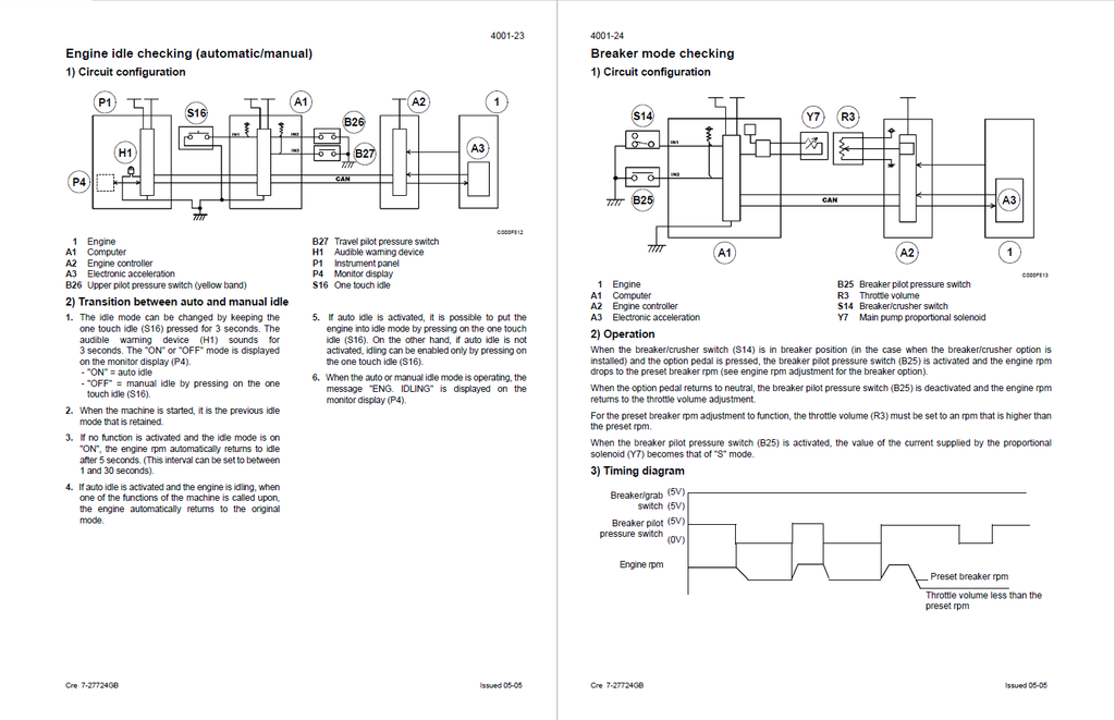
- Engine idle checking (automatic/manual)
- Breaker mode checking
- Automatic engine preheat
- Auto engine warm-up
- Idle checking using the battery voltage and the coolant temperature
- Engine emergency stop
- Back-up mode
- Function locking
- Power boost
- Swing brake
- Travel mode
- Machine condition
- Diagnostic code
- Machine history
- Re-initialisation
- WARNING MESSAGES
- Message display
- EXCAVATOR MODEL SELECTION PROCEDURE
- Changing the language code
- CHANGING THE ACCESS CODE FOR THE ANTI-THEFT SYSTEM
- TROUBLESHOOTING
- Prior inspections
- Reading the organisation charts
- Procedures
- Low fuel
- Add coolant solution
- Travel
- ELECTRICAL INSPECTION OF COMPONENTS
- Inspection equipment
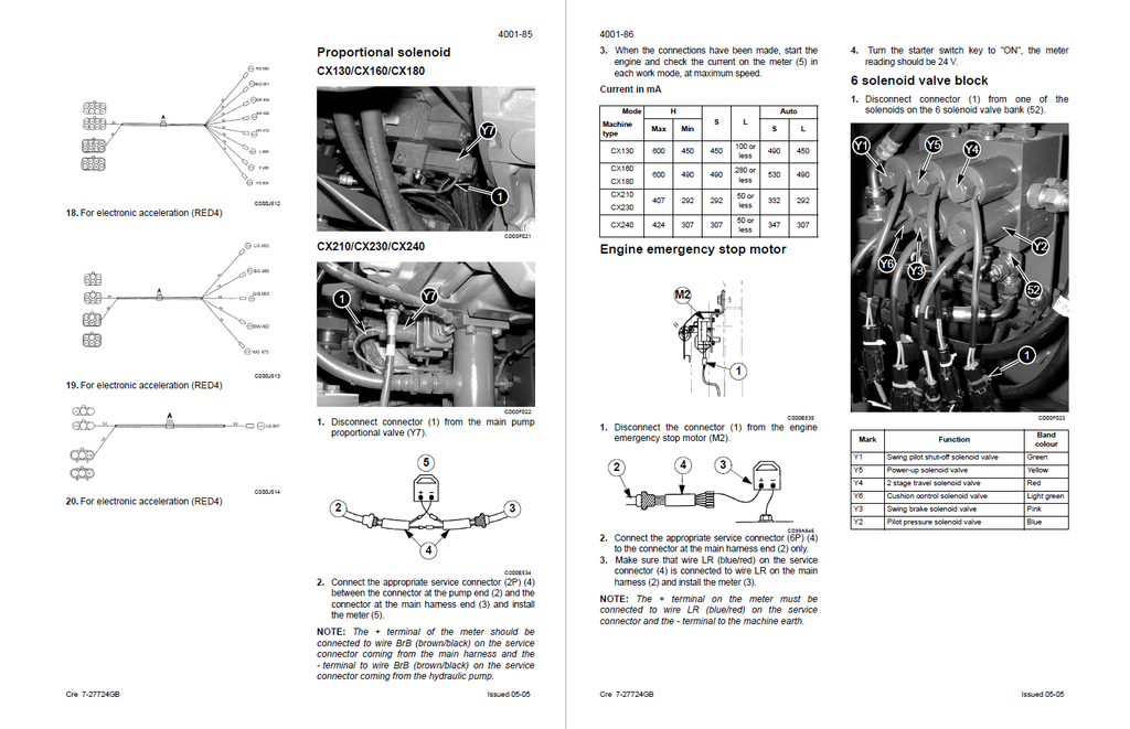
- Proportional solenoid
- Pressure sensor
- REMOVAL AND INSTALLATION OF THE TRACKS SET
- SPECIFICATIONS
- SPECIAL TORQUE SETTINGS
- SPECIAL TOOLS
- TRACKS SET
- Description
- Removal
- Reconditioning
- Disassembly
- Inspection
- Assembly
- Installation
- UPPER ROLLER
- Description
- Removal
- Reconditioning
- Disassembly
- Inspection
- Assembly
- DRIVE TRAIN
- Drive motor and final drive transmission removal and installation
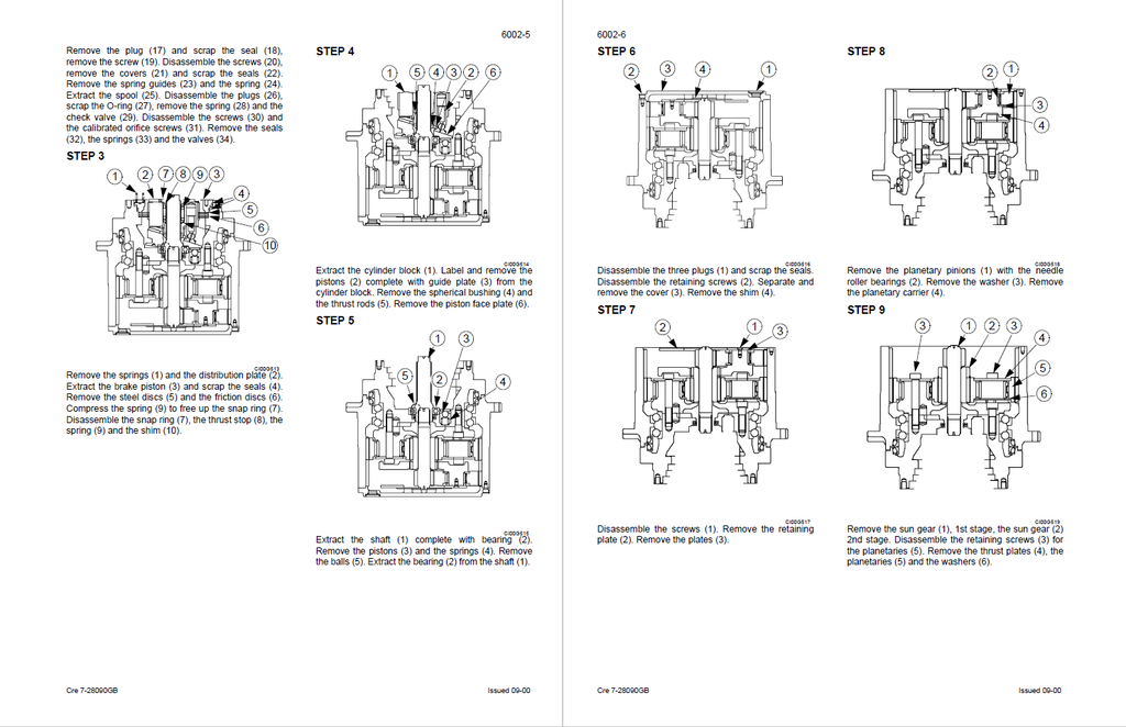
- DISASSEMBLY AND ASSEMBLY OF THE TRAVEL MOTOR/REDUCTION GEAR ASSEMBLY
- SPECIFICATIONS
- SWING REDUCTION GEAR
- SPECIFICATIONS
- HYDRAULIC SYSTEM
- DEPRESSURISING AND DECONTAMINATING THE HYDRAULIC SYSTEM, USE OF THE VACUUM PUMP AND BLEEDING THE COMPONENTS
- SPECIAL TOOLS
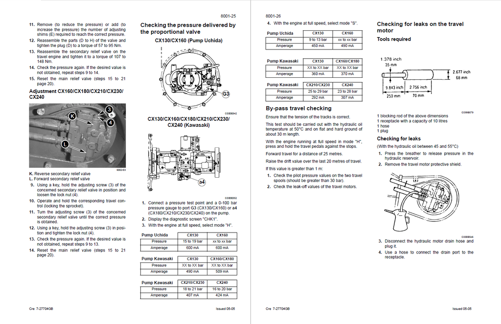
- SPECIFICATIONS, TROUBLESHOOTING, CHECKS AND HYDRAULIC PRESSURE SETTINGS
- SPECIFICATIONS
- Display on diagnostic screen "CHK1"
- Warming up the engine
- Warming up the hydraulic fluid
- CHECKING AND PRESSURE SETTING PROCEDURE
- CYLINDERS
- Description
- Removal
- Installation
- BUCKET CYLINDER
- Description
- Removal
- Installation
- REMOVAL AND INSTALLATION OF THE SWING MOTOR
- SPECIFICATIONS
- SPECIAL TORQUE SETTINGS
- SWING MOTOR
- Removal and installation
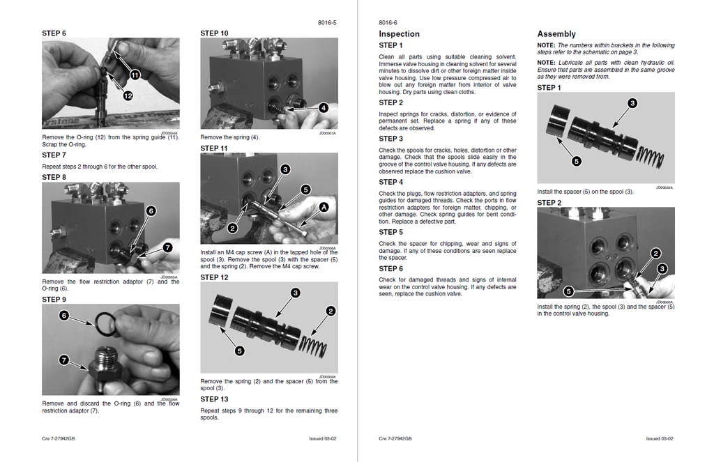
- SIX SOLENOID VALVES BLOCK
- Identifying the ports and the solenoid valves
- Section
- Disassembly and assembly
- Inspection
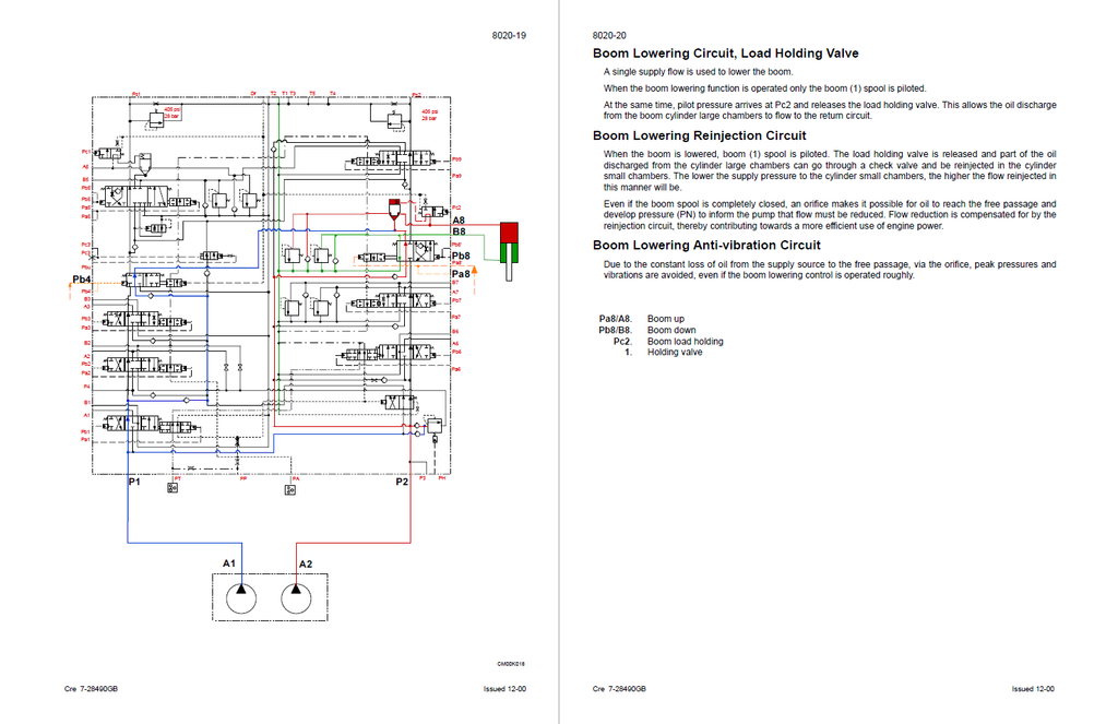
- HYDRAULIC CIRCUITS
- Function List
- Controls in Neutral
- High Speed Travel Circuit
- Low Speed Travel Circuit
- Straight Line Travel Circuit
- Swing Circuit
- Variable Priority Valve Circuit
- Boom Raising Circuit
- Boom Lowering Circuit, Load Holding Valve
- Boom Lowering Reinjection Circuit
- Boom Lowering Anti-vibration Circuit
- Dipper Extending Circuit
- Dipper Retracting Circuit
- Dipper Retracting Reinjection Circuit
- Bucket Opening Circuit
- Bucket Closing Circuit
- Crusher Circuit
- Breaker Circuit
- DEPRESSURISING AND DECONTAMINATING THE HYDRAULIC SYSTEM, USE OF THE VACUUM PUMP AND BLEEDING THE COMPONENTS
- UPPERSTRUCTURE, TURNTABLE AND COUNTERWEIGHT
- SPECIAL TORQUE SETTINGS
- SPECIFICATIONS
- UPPERSTRUCTURE
- Inspection
- Removal
- Installation
- BOOM, DIPPER AND BUCKET
- DIPPER
- Description
- Removal
- Installation
- BOOM
- Description
- Removal
- Installation
- DIPPER
- SEAT AND SAFETY BELT
- SPECIFICATIONS
- OPERATOR’S SEAT
- Description
- Removal
- Installation
- CAB AND CAB EQUIPMENT
- SPECIFICATIONS
- SPECIAL TORQUE SETTINGS
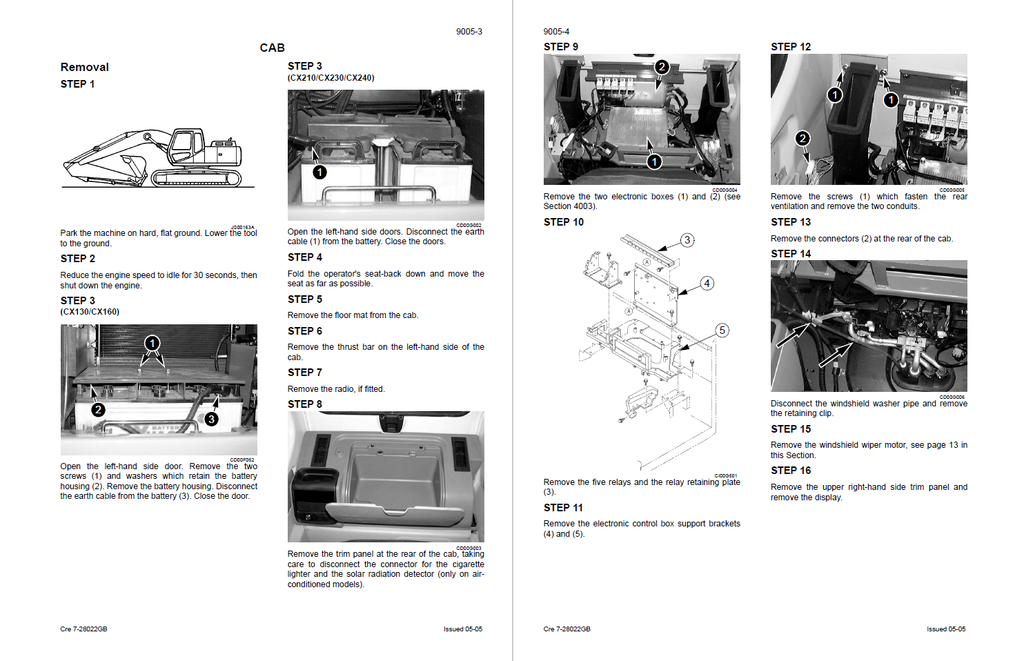
- CAB
- Removal
- Installation
- AIR CONDITIONER TROUBLESHOOTING AND SYSTEM CHECKS
- SAFETY PROCEDURES
- SPECIAL TOOLS
- ELECTRICAL SCHEMATIC
- PRE-STUDIES