

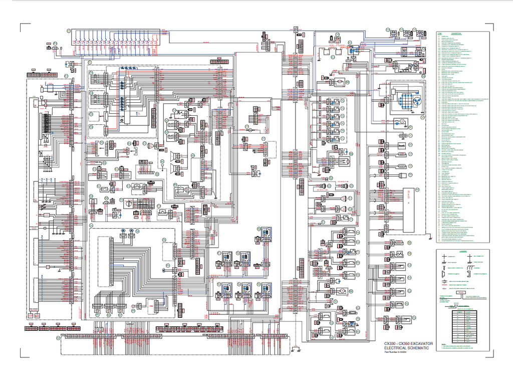
CASE Construction CX330, CX350 Crawler Excavator Service Manual 9-42890 English
Official Manual Overview
Command the heavy earthmoving sector with this definitive OEM Service Manual, engineered exclusively for the CASE CX330, CX350, and CX460 Crawler Excavators. Designed for elite dealership technicians, this master reference bypasses routine maintenance to deliver uncompromising, surgical reconstruction protocols for the entire chassis, undercarriage, and complex hydraulic architecture. It provides absolute fluid metrology, dictating precise secondary relief tuning at 212 bar (21.2 MPa) and main relief power boost capabilities up to 392 bar (39.2 MPa), alongside absolutely staggering fastening specifications—including a crushing 9040 Nm torque requirement for the boom cylinder piston nut and 1685-1960 Nm for the massive M33 counterweight bolts. Furthermore, it transforms the cabin monitor into an advanced diagnostic interrogation terminal, mapping exact keystrokes to unlock hidden CHK and DIAG engineering screens for deep CAN-bus and proportional solenoid troubleshooting. Please note: While external engine checks and ECM diagnostics are exhaustively covered, deep internal block teardowns for the Isuzu 6HK1-series diesel engines are explicitly redirected to a dedicated Engine Service Manual.
- Brands: CASE Construction
- Equipment Type: Crawler Excavator
- Manuals Type: Service Manual
- Machine Model: CX330, CX350
- Serial Number: N/R
- Region: N/R
- Book Code: 9-42890
- Issued: Printed in France, March 2002
- Language: English
- Pages: 623
- File Format: PDF (Searchable)
Core Selling Points
- Dealership-Grade Hydraulic Calibration: Command the massive fluid architecture of the 30-to-40-ton class machinery. This literature dictates exact tuning procedures using the Multi-Handy 2051 digital tester and CAS 30038 flow kits. It strictly mandates verifying the main pump P1/P2 delivery at exactly 34.5 MPa (345 bar) and tuning the negative pressure control to a rigid 0.25 MPa baseline at 1850 rpm to restore factory breakout force.
- Deep-Level Electronic Interrogation: Transform the cabin monitor into an advanced diagnostic terminal. The manual provides the exact keystroke sequences to unlock the hidden CHK1-6 and DIAG1-6 engineering screens. Mechanics can instantly decode proprietary CAN-bus network failures (Fault Code M0090) or pinpoint an open circuit in the electronic regulator's linear motor (Fault Code E0031) without relying on external computer hookups.
- Extreme Structural Fastening Architectures: Safeguard against catastrophic mechanical separation under severe mining and trenching loads. The documentation outlines the mandatory teardown and reconstruction matrices for all heavy assemblies, dictating immense torque applications—including a crushing 9040 Nm requirement for the boom cylinder piston nut, 431 Nm for the Uchida main pump body screws, and 324 Nm for the travel motor hardware.
Features & Highlights
- Micro-Tolerance Pump & Motor Reconstruction: Rebuild the Uchida main hydraulic pumps and travel motors with absolute mathematical certainty. This guide defines rigid wear limits, condemning the CX460 pump cylinder assembly the moment piston-to-bore clearance exceeds 0.078 mm, and demanding a surface roughness of exactly 0.8 Ra or less for the valve plate sliding surfaces.
- Surgical Sensor & ECM Metrology: Eradicate phantom electrical draws and blind parts swapping. Utilizing the CAS-30039 service connector kit, technicians are provided with absolute resistance benchmarks—such as proving the health of the coolant thermistor by verifying a strict 6.08 kΩ reading at 20°C, which must drop to exactly 0.91 kΩ at 80°C to guarantee ECM synchronization.
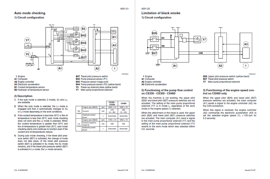
- Dynamic Flow & Proportional Solenoid Logic: Navigating the complex 6-solenoid valve bank is made straightforward. The manual extensively maps out the internal PWM current logic for the main pump proportional solenoid (Y7), detailing how the engine controller (A2) modulates current from 490 mA in standard mode up to exactly 600 mA during maximum H-mode power boost operations.
Problem Solver
- Resolves Catastrophic Drive Train Failures: The step-by-step teardown instructions for the planetary reduction gears and travel motors prevent fatal reassembly mistakes. It provides absolute micrometer inspection thresholds, demanding the immediate replacement of piston shoes if the looseness of the crimping area exceeds the critical 0.3 mm allowable limit, permanently curing travel shudder and loss of torque.
- Cures Sudden Engine Back-Up Mode Drops: Troubleshoot electronic throttle and governor assistance errors definitively. The diagnostic trees guide mechanics through the logic of the RED4 electronic acceleration module (A3), helping isolate elusive power loss to a faulty engine rpm sensor (B41) or corrupted serial communication lines between the main computer and the fuel pump.
- Eradicates False Thermal Shutdowns: Resolves hidden overheating alarms that paralyze machine operation. The electrical troubleshooting matrices instruct builders to verify the exact trip logic of the warning system, confirming that the high-temperature alert correctly triggers only when coolant actually exceeds 105°C or hydraulic oil hits 98°C, instantly isolating a physical cooling failure from a destroyed wiring harness.
Important Pre-Purchase Advisories
- Complete "Large Format" Schematics Included: Unlike many digital copies that omit physical fold-out inserts, this specific manual fully incorporates the original large-format electrical wiring diagrams and complex hydraulic circuit charts (OEM Reference 7-29440GB / Pocket section) at the end of the file, delivering 100% unbroken end-to-end component routing.
- Dedicated Engine Block Focus: In strict adherence to the manufacturer's publication strategy, this manual exhaustively covers engine removal, installation, electronic acceleration modules, and external sensor diagnostics. However, deep internal mechanical teardowns of the Isuzu diesel engine block are explicitly redirected to a dedicated Engine Service Manual.
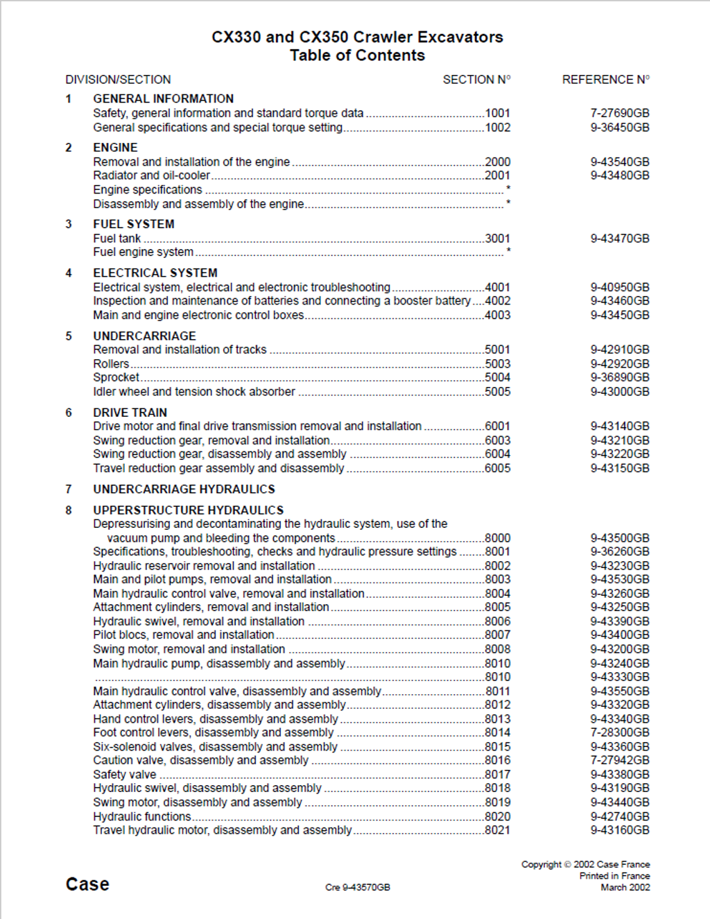
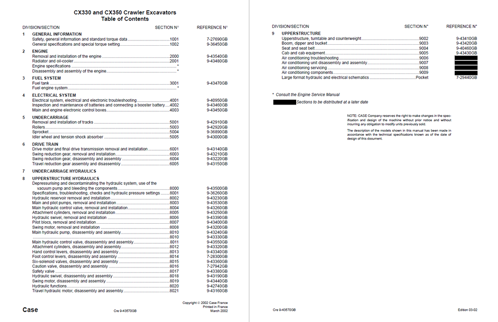
Table of Contents
- GENERAL INFORMATION
- Safety, general information and standard torque data
- General information
- Safety
- Standard torque data for cap screws and nuts
- General specifications and special torque setting
- Type, serial number and year of manufacture of the machine
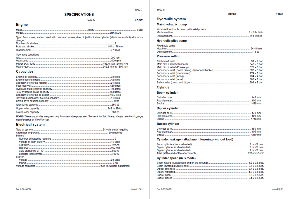
- Specifications
- Weight of components
- Dimensions and wear limits of attachment mobile joints
- Special torque settings
- Machine overall dimensions
- Safety, general information and standard torque data
- ENGINE
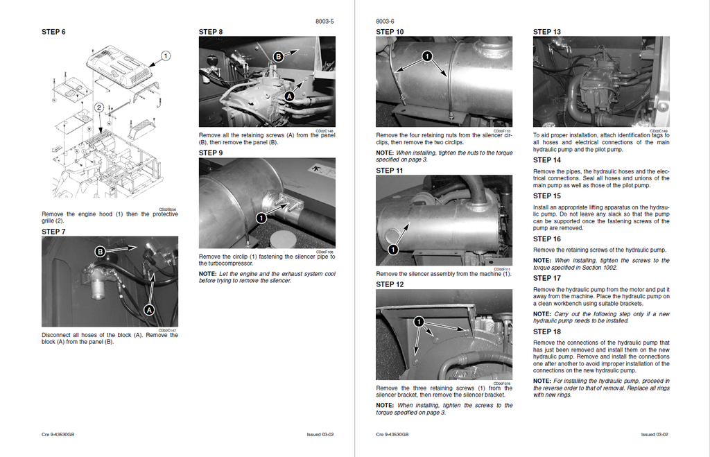
- Removal and installation of the engine
- Radiator and oil-cooler
- Specifications
- Changing the radiator or the oil-cooler
- FUEL SYSTEM
- Fuel tank
- ELECTRICAL SYSTEM
- Electrical system, electrical and electronic troubleshooting
- Specifications
- Special tools
- General location of the components (outside the cab)
- General location of the components (inside the cab)
- Operating principles
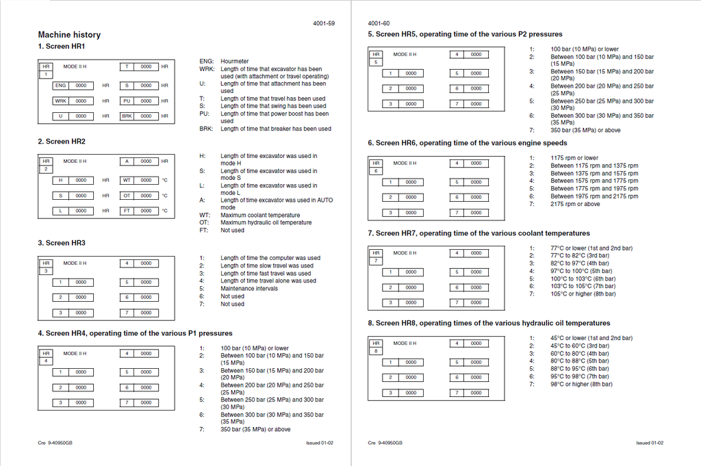
- Access and contents of monitor displays (Diagnostic mode)
- Warning messages
- Excavator model selection procedure
- Changing the access code for the anti-theft system
- Troubleshooting
- Electrical inspection of components
- Inspection and maintenance of batteries and connecting a booster battery
- Specifications
- Maintenance
- Main and engine electronic control boxes
- Main electronic control box and engine electronic control box
- Electrical system, electrical and electronic troubleshooting
- UNDERCARRIAGE
- Removal and installation of tracks
- Specifications
- Special torque settings
- Special tools
- Tracks set
- Upper roller
- Rollers
- Lower roller
- Upper roller
- Sprocket
- Sprocket
- Idler wheel and tension shock absorber
- Track tension cylinder
- Removal and installation of tracks
- DRIVE TRAIN
- Drive motor and final drive transmission removal and installation
- Travel motor/reduction gear assembly
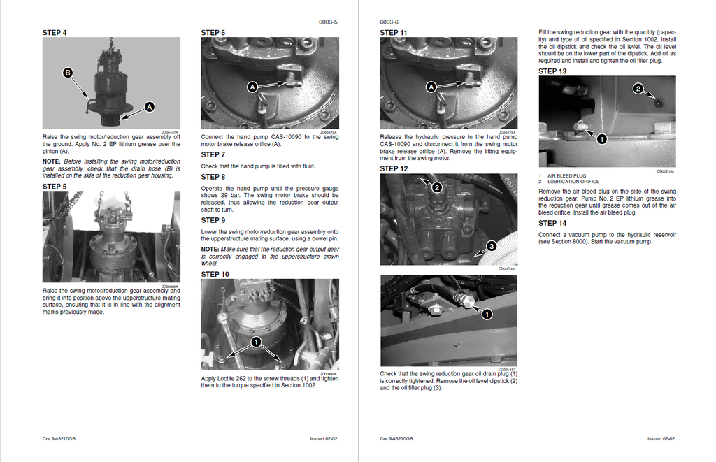
- Swing reduction gear, removal and installation
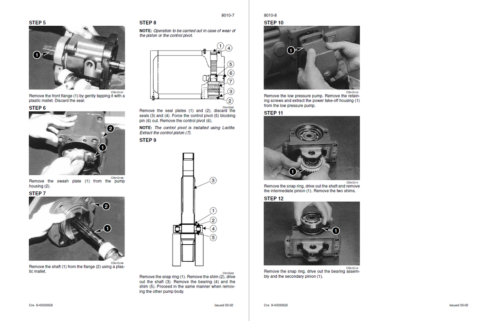
- Swing reduction gear, disassembly and assembly
- Special torque settings
- Swing reduction gear
- Travel reduction gear assembly and disassembly
- Reduction gear
- Drive motor and final drive transmission removal and installation
- UNDERCARRIAGE HYDRAULICS
- UPPERSTRUCTURE HYDRAULICS
- Depressurising and decontaminating the hydraulic system, use of the vacuum pump and bleeding the components
- Special tools
- Releasing pressure in the hydraulic system
- Bleeding air from the main hydraulic system components
- Vacuum pump
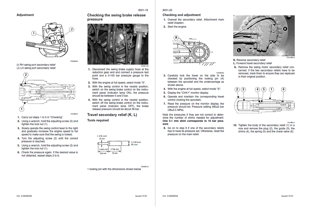
- Specifications, troubleshooting, checks and hydraulic pressure settings
- Specifications
- Special tools
- Identification of hydraulic components
- Preparation before inspection
- Location of secondary relief valves
- Main pilot system relief
- Troubleshooting
- Hydraulic reservoir removal and installation
- Main and pilot pumps, removal and installation
- Main hydraulic pump
- Pilot pump
- Main hydraulic control valve, removal and installation
- Attachment cylinders, removal and installation
- Attachment cylinders
- Bucket cylinder
- Hydraulic swivel, removal and installation
- Pilot blocs, removal and installation
- Swing motor, removal and installation
- Main hydraulic pump, disassembly and assembly
- Specifications
- Special torque settings
- Wear inspection
- Tools required
- Identifying the components
- Identifying the ports
- Regulation control
- Removal
- Assembly
- Main hydraulic control valve, disassembly and assembly
- Control valve
- Attachment cylinders, disassembly and assembly
- Special tools
- Cylinders
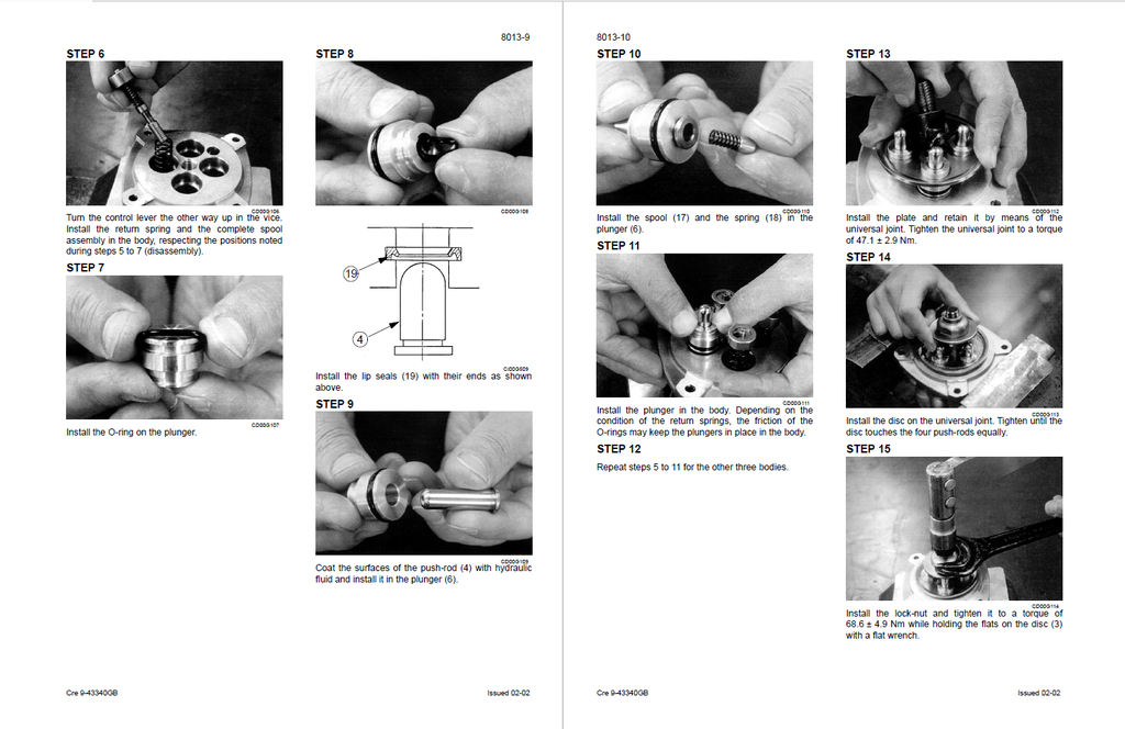
- Hand control levers, disassembly and assembly
- Specifications
- Control lever
- Foot control levers, disassembly and assembly
- Control pedal
- Six-solenoid valves, disassembly and assembly
- Six solenoid valves block
- Caution valve, disassembly and assembly
- Safety valve
- Hydraulic swivel, disassembly and assembly
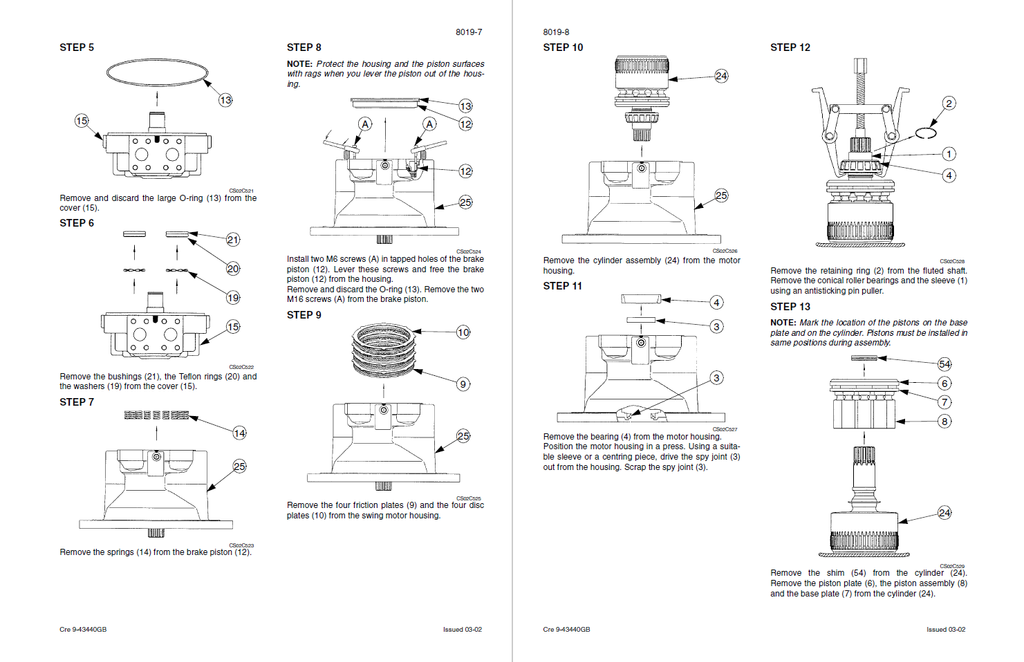
- Swing motor, disassembly and assembly
- Specifications
- Torque settings
- Hydraulic swing motor
- Hydraulic functions
- Travel hydraulic motor, disassembly and assembly
- Specifications
- Special torques
- Travel motor
- Brake valve
- Depressurising and decontaminating the hydraulic system, use of the vacuum pump and bleeding the components
- UPPERSTRUCTURE
- Upperstructure, turntable and counterweight
- Upperstructure
- Boom, dipper and bucket
- Specifications
- Bucket
- Dipper
- Boom
- Seat and seat belt
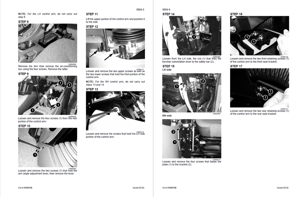
- Cab and cab equipment
- Specification
- Special torque settings
- Cab
- Heater
- Air conditioning unit disassembly and assembly
- Large format hydraulic and electrical schematics
- Upperstructure, turntable and counterweight