

CASE Construction CX40B PH05-03501~, CX50B PJ04-03001~ Crawler Excavator Shop Manual 9-91940 English
Official Manual Overview
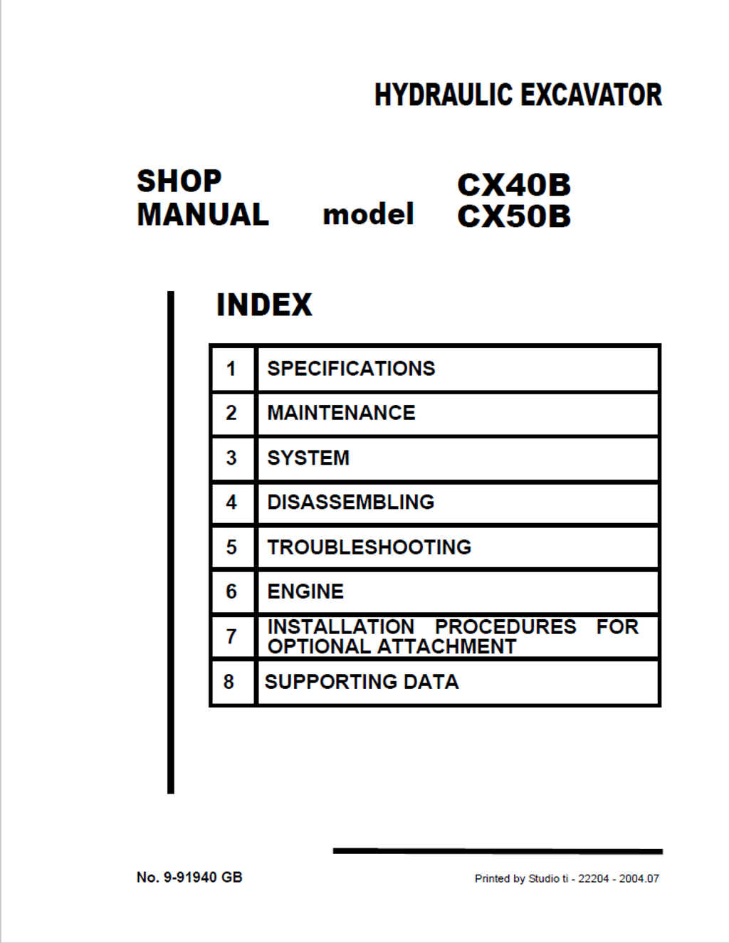
Empower your workshop with the definitive OEM Shop Manual designed exclusively for the CASE CX40B and CX50B Compact Excavators. Moving far beyond basic maintenance, this master blueprint delivers dealership-level teardown and calibration protocols for the machine's core fluid power systems—detailing exact 23.0 MPa (3340 psi) main relief settings for the AP2D25LV1RS7 variable displacement axial piston pumps and the BCV65-AQ10 11-spool control valves. Crucially, this volume eliminates the need for secondary powertrain literature by embedding the unabridged factory overhaul documentation for the entire Yanmar TNV diesel engine family (spanning from the 3TNV82A up to the massive 4TNV106T). Complete with micrometer-level metrology for crankshaft journals, step-by-step rebuilding procedures for the GM06VA hydrostatic travel motors, and exhaustive electrical harness pin-out matrices, this uncompromising guide guarantees absolute precision when restoring your crawler chassis and hydraulics to factory specifications.
- Brands: CASE Construction
- Equipment Type: Crawler Excavator
- Manuals Type: Shop Manual
- Machine Model: CX40B, CX50B
- Serial Number: PH05-03501~ (for CX40B), PJ04-03001~ (for CX50B)
- Region: N/R
- Book Code: 9-91940
- Issued: Printed by Studio ti - 2004.07
- Language: English
- Pages: 780
- File Format: PDF (Searchable)
Core Selling Points
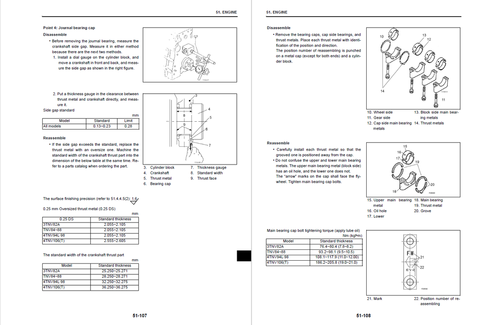
- Granular Powertrain & Actuator Rebuilds: Do not rely on generalized specifications. This master manual embeds the unabridged factory teardown protocols for the entire Yanmar TNV diesel series (including the 3TNV82A through 4TNV106T) alongside the machine's hydrostatic drives. It dictates absolute machining thresholds, condemning the 3TNV82A cylinder bore if wear exceeds 82.200 mm, and mandating replacement of the GM06VA travel motor output shaft if spline wear reaches just 25 µm (0.001 in).
- Precision Fluid Power Calibration: Restore ultimate breakout force and flow priority. The guide maps out strict benchmarking procedures, instructing technicians to utilize a 49 MPa (7100 psi) test gauge at the PF1/4 detecting ports to verify the AP2D25LV1RS7 pump's main relief valves are locked at exactly 23.0 MPa (3340 psi) yielding a 57.1 L/min flow rate, while setting the pilot circuit strictly to 3.5 MPa.
- Uncompromising Structural Fastening: Reconstruct heavy-duty undercarriage and chassis elements using exact OEM torque metrics. The literature leaves zero room for structural failure, enforcing massive tightening specifications such as 1070 Nm (789 lbf-ft) for M36 coarse thread capscrews, 188.0 to 197.8 Nm for the 4TNV106(T) cylinder head bolts, and a strict 181 Nm application with Loctite #262 for the travel motor fixing hardware.
Features & Highlights
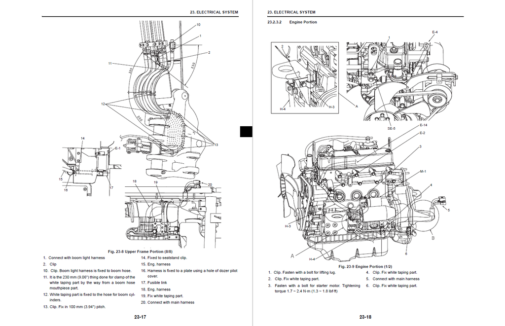
- Pin-Level Electrical Topologies: Take absolute control over the machine's nervous system. The manual decodes complex digital routing with exhaustive harness matrices, detailing exact pin-by-pin terminal definitions (such as the CN-101F and 3PAF-090H connectors). It empowers mechanics to physically trace 12-volt continuity through color-coded wiring, such as the Yellow/Green (YG) and Yellow/White (YW) circuits, to isolate elusive voltage drops.
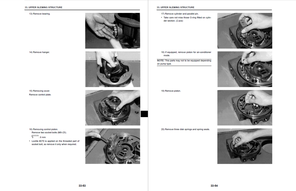
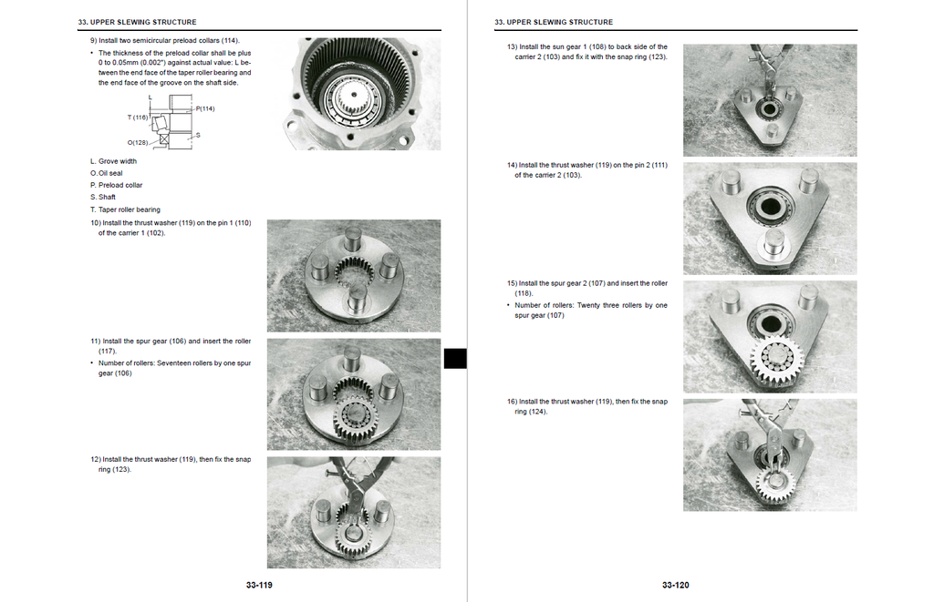
- Micro-Tolerance Drivetrain Teardown: Rebuild the PLC-120-18B slewing motor and BCV65-AQ10 11-spool control valve without diagnostic guesswork. The text provides step-by-step disassembly charts, strictly regulating internal wear limits—such as condemning the hydraulic motor cylinder and valve plate if sliding surface wear depth exceeds 20 µm (0.0008 in).
- Proprietary Wear Registries & Tooling: Equip your shop with the precise parameters required for undercarriage and engine overhaul. The manual provides an exhaustive steel and rubber crawler track wear matrix, demanding track pin and bushing replacement if clearance reaches 1.0 mm (0.04 in). It also specifies exact OEM tooling setups, such as using a Flex-Hone at a 30 to 40-degree angle for cylinder liner re-honing.
Problem Solver
- Defeating Hydrostatic Degradation: Stop blindly replacing expensive planetary final drives. The manual empowers technicians to scientifically evaluate internal motor efficiency. By measuring the casing drain volume, mechanics can definitively condemn the travel motor if the hydraulic drain exceeds 0.5 L/min at 10 rpm under a 1.57 MPa (228 psi) drive pressure, pinpointing catastrophic internal failure before a total lockup occurs.
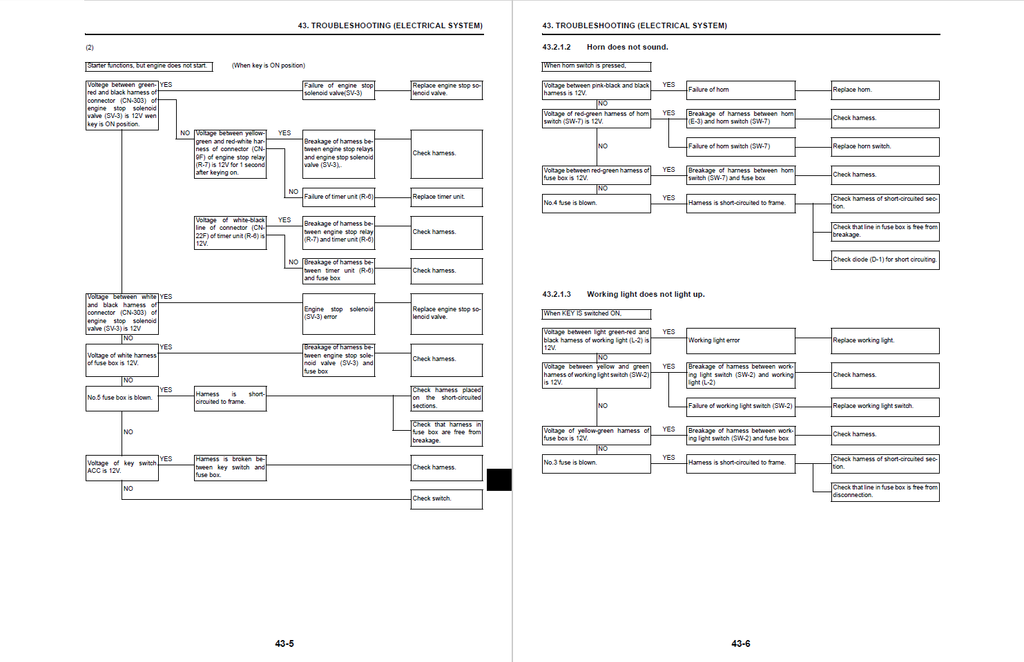
- Eradicating Elusive Electrical Faults: Transform erratic power loss into calculated repair sequences. Using the provided diagnostic logic trees, technicians can trace a dead working light or malfunctioning fuel gauge directly to short circuits in the frame that blow the No.3 or No.6 fuses, eliminating the need to unnecessarily replace the entire gauge cluster or switch assemblies.
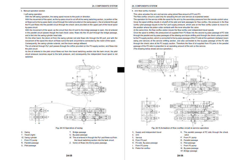
- Isolating Attachment Power Loss: Systematically narrow down sluggish boom or arm movements. The troubleshooting flowcharts teach operators how to scientifically differentiate between a failing pilot pump, a stuck flow conflux valve, or internal cylinder piston bypass leakage, ensuring you only replace the specific component causing the operational failure.
Important Pre-Purchase Advisories
- Complete Engine Integration: Unlike standard heavy equipment manuals, this comprehensive volume integrates the full Yanmar TNV Engine Shop Manual directly into the chassis documentation (Section 51). You will not need to source a separate engine blueprint.
- Schematic Location Notice: Please note that the high-resolution electrical harness diagrams (Fig. 71-13) and the complete fold-out hydraulic circuit maps are physically consolidated in the "Supporting Data" (Section 71) at the end of the publication.
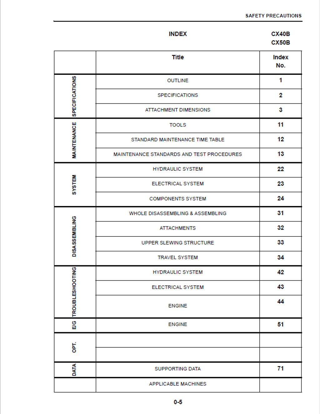
Table of Contents
- OUTLINE
- GENERAL PRECAUTIONS FOR REPAIRS
- PREPARATION BEFORE DISASSEMBLING
- SAFETY IN DISASSEMBLING AND ASSEMBLING
- DISASSEMBLING AND ASSEMBLING HYDRAULIC EQUIPMENT
- ELECTRICAL EQUIPMENT
- HYDRAULIC PARTS
- WELDING REPAIR
- ENVIRONMENTAL MEASURE
- GENERAL PRECAUTIONS FOR REPAIRS
- SPECIFICATIONS
- COMPONENTS NAME
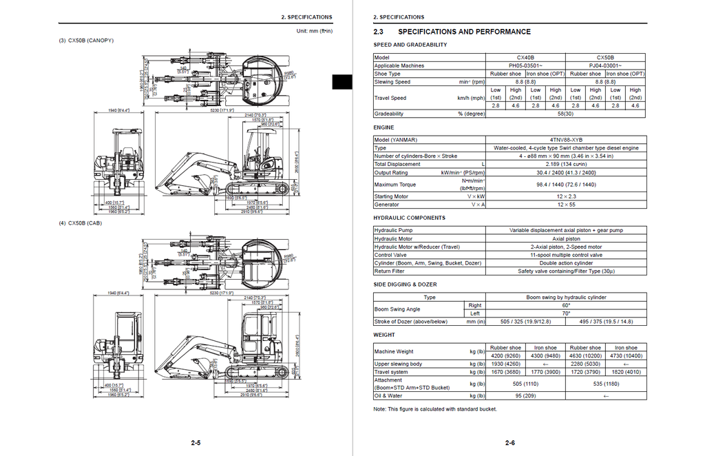
- MACHINE DIMENSIONS
- SPECIFICATIONS AND PERFORMANCE
- TYPE OF CRAWLER SHOES
- TYPE OF BUCKET
- SPECIFICATIONS
- ENGINE PERFORMANCE CURVE
- ATTACHMENT DIMENSIONS
- BOOM
- BOOM DIMENSIONAL DRAWINGS
- ARM
- ARM DIMENSIONAL DRAWINGS
- ARM MAINTENANCE STANDARDS
- BUCKET
- BUCKET DIMENSIONAL DRAWINGS
- DETAIL DIMENSIONAL DRAWINGS OF LUG SECTION
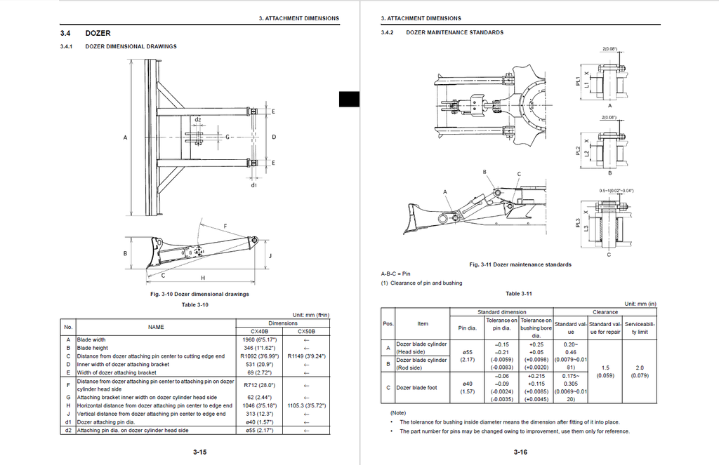
- DOZER
- DOZER DIMENSIONAL DRAWINGS
- DOZER MAINTENANCE STANDARDS
- SWING
- SWING BRACKET DIMENSIONAL DRAWINGS
- SWING PORTION MAINTENANCE STANDARDS
- BOOM
- TOOLS
- TORQUE SPECIFICATIONS FOR CAPSCREWS & NUTS
- METRIC COARSE THREAD STANDARD TIGHTENING TORQUE VALUES
- METRIC FINE THREAD STANDARD TIGHTENING TORQUE VALUES
- TORQUE SPECIFICATIONS FOR CAPSCREWS & NUTS
- STANDARD MAINTENANCE TIME TABLE
- MAINTENANCE STANDARDS AND TEST PROCEDURES
- HOW TO USE MAINTENANCE STANDARDS AND PRECAUTIONS
- PERFORMANCE INSPECTION STANDARD TABLE
- STANDARD VALUE TABLE
- MEASURING ENGINE SPEED
- ENGINE SPEED MEASUREMENT
- MEASURING HYDRAULIC OIL PRESSURE
- HYDRAULIC SYSTEM
- SUMMARY
- FUNCTION AND FEATURES OF HYDRAULIC CIRCUIT
- HYDRAULIC CIRCUITS AND COMPONENT MODELS
- HYDRAULIC CIRCUIT OPERATION
- COLOR CODING STANDARD FOR HYDRAULIC
- NEUTRAL CIRCUIT
- TRAVEL OPERATING CIRCUIT
- SLEW OPERATING CIRCUIT
- BUCKET OPERATING CIRCUIT
- BOOM OPERATING CIRCUIT
- ARM OPERATING CIRCUIT
- SWING OPERATING CIRCUIT
- DOZER OPERATING CIRCUIT
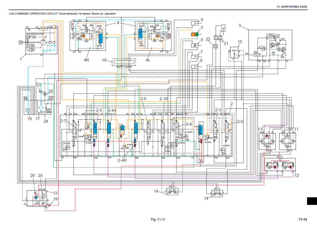
- TRAVEL / DOZER COMBINED OPERATING CIRCUIT
- TRAVEL / BOOM COMBINED OPERATING CIRCUIT
- SUMMARY
- ELECTRICAL SYSTEM
- HOW TO READ CIRCUIT DIAGRAM AND HARNESS CONNECTION
- ELECTRIC CIRCUIT DIAGRAM
- HARNESS CONNECTION
- ELECTRICAL EQUIPMENT & HARNESS
- ELECTRICAL EQUIPMENT LIST
- HARNESS & CABLE LIST
- ARRANGEMENT DRAWING FOR COMPONENTS & HARNESS
- HOW TO READ CIRCUIT DIAGRAM AND HARNESS CONNECTION
- COMPONENTS SYSTEM
- HYDRAULIC COMPONENTS
- HYDRAULIC PUMP
- PILOT VALVE (ATT)
- PILOT VALVE (TRAVEL)
- CONTROL VALVE
- SLEWING MOTOR
- TRAVEL MOTOR
- SWIVEL JOINT
- CYLINDER
- ELECTRICAL EQUIPMENT
- ELECTRICAL EQUIPMENT LIST
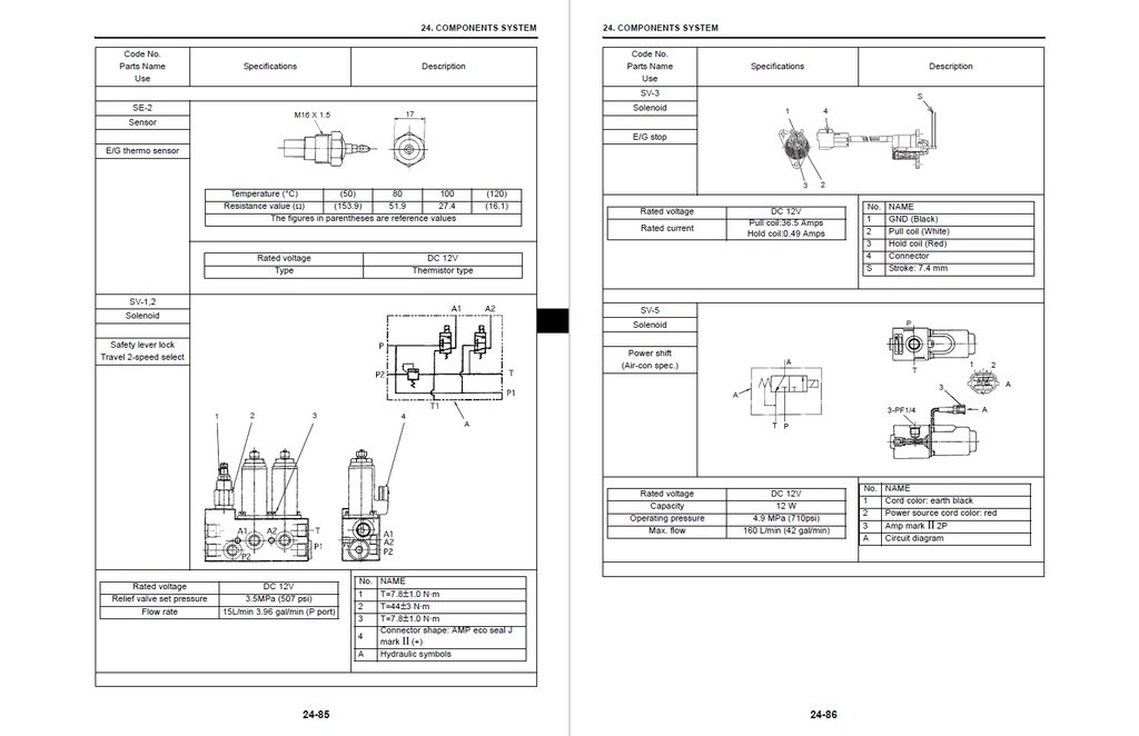
- SPECIFICATIONS ELECTRICAL EQUIPMENT
- HYDRAULIC COMPONENTS
- WHOLE DISASSEMBLING & ASSEMBLING
- SPECIFICATION OF TIGHTENING TORQUE
- ATTACHMENTS
- REMOVING AND INSTALLING
- ATTACHMENT ASSEMBLY AND NAME
- BUCKET
- ARM
- BOOM
- SWING
- DOZER
- DISASSEMBLING AND ASSEMBLING
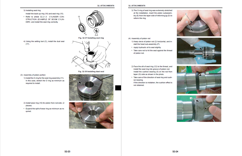
- CYLINDER
- REMOVING AND INSTALLING
- UPPER SLEWING STRUCTURE
- REMOVING AND INSTALLING
- CANOPY / CAB
- GUARD (COVER)
- FLOOR PLATE ASSEMBLY
- BATTERY
- COUNTERWEIGHT
- PUMP
- CONTROL VALVE
- SOLENOID VALVE
- FUEL TANK
- HYDRAULIC OIL TANK
- AIR CLEANER
- GENERATOR
- MUFFLER
- CONTROL STAND
- STARTER
- RADIATOR
- ENGINE
- PILOT VALVE
- SLEWING MOTOR
- SWIVEL JOINT
- UPPER FRAME
- DISASSEMBLING AND ASSEMBLING
- HYDRAULIC PUMP
- CONTROL VALVE
- PILOT VALVE (Attachment)
- PILOT VALVE (TRAVEL)
- SLEWING MOTOR
- SWIVEL JOINT
- REMOVING AND INSTALLING
- TRAVEL SYSTEM
- REMOVING AND INSTALLING
- NAME OF TRAVEL SYSTEM PARTS
- CRAWLER
- UPPER ROLLER
- MAINTENANCE STANDARDS
- TOOLS AND JIGS
- LOWER ROLLER
- FRONT IDLER
- IDLER ADJUSTER
- SPROCKET
- TRAVEL MOTOR
- SLEWING BEARING
- DISASSEMBLING AND ASSEMBLING
- TRAVEL MOTOR
- REMOVING AND INSTALLING
- TROUBLESHOOTING
- HYDRAULIC SYSTEM
- TROUBLE DIAGNOSIS: HYDRAULIC
- TROUBLESHOOTING
- ATTACHMENT
- TRAVEL OPERATION
- SLEWING OPERATION
- PUMP
- ELECTRICAL SYSTEM
- TROUBLE DIAGNOSIS: ELECTRIC SYSTEM
- TROUBLESHOOTING
- GENERAL
- ATTACHMENT OPERATION
- TRAVEL OPERATION
- DECELERATION
- ENGINE
- ELECTRICAL EQUIPMENT
- ELECTRICAL EQUIPMENT LIST
- ELECTRICAL EQUIPMENT
- HYDRAULIC SYSTEM
- ENGINE
- GENERAL
- INSPECTION AND ADJUSTMENT
- TROUBLESHOOTING
- DISASSEMBLY, INSPECTION AND REASSEMBLY OF ENGINES
- LUBRICATION SYSTEM
- COOLING SYSTEM
- FUEL INJECTION PUMP/GOVERNOR
- TURBOCHAGER: DISASSEMBLY, INSPECTION AND REASSEMBLY
- STARTING MOTOR
- ALTERNATOR
- ELECTRIC WIRING
- SERVICE STANDARDS
- TIGHTENING TORQUE FOR BOLTS AND NUTS
- SUPPORTING DATA
- HYDRAULIC CIRCUIT DIAGRAM
- STANDARD SPECIFICATION
- HYDRAULIC CIRCUIT OPERATION
- SCHEMATIC PIPING FOR HYDRAULIC SYSTEM
- ELECTRIC CIRCUIT DIAGRAM
- HYDRAULIC CIRCUIT DIAGRAM