

CASE Construction CX460 Crawler Excavator Service Manual 9-43840 English
Official Manual Overview
Take absolute command over the massive CASE CX460 Crawler Excavator with this uncompromising OEM Service Manual. Engineered exclusively for master dealership technicians, this heavy-duty reference bypasses basic maintenance to deliver hardcore reconstruction protocols for the undercarriage, drive train, and complex hydraulic architecture. It demands absolute micrometer precision, explicitly condemning the Kawasaki main pump cylinder assembly the moment piston-to-bore clearance exceeds exactly 0.078 mm, and mandates massive fastening forces—including 1765-2010 Nm for the 9.18-ton counterweight bolts and 1236-1510 Nm for the heavy-duty track pads. Furthermore, it transforms the cabin monitor into an advanced interrogation terminal, mapping exact keystrokes to access hidden CHK and DIAG engineering screens for decoding proprietary CAN-bus networks and the Isuzu 6SD1XQB engine controller. Please note: In strict adherence to the manufacturer's publication strategy, while external sensor diagnostics and complete engine removal are exhaustively detailed, deep internal mechanical teardowns of the diesel block are explicitly redirected to a dedicated engine manual.
- Brands: CASE Construction
- Equipment Type: Crawler Excavator
- Manuals Type: Service Manual
- Machine Model: CX460 (Includes electrical systems data for CX330 / CX350)
- Serial Number: N/R
- Region: N/R
- Book Code: 9-43840
- Issued: Printed in France, October 2002
- Language: English
- Pages: 580
- File Format: PDF (Searchable)
Core Selling Points
- Unrestricted ECM Interrogation: Bypass proprietary dealership software using the cabin monitor's hidden diagnostic architecture. The manual explicitly maps out exact keystroke pathways to access the DIAG1-6 and CHK1-6 engineering menus, empowering mechanics to instantly decode CAN-bus communication failures (Code M0090) or electronic regulator rack position detector faults (Code E0032) in real-time.
- Kawasaki Pump Micrometer Reconstruction: Rebuild the primary fluid power cores with absolute mathematical certainty. This volume establishes uncompromising wear thresholds for the heavy-duty components, mandating cylinder assembly replacement if the piston-to-bore clearance exceeds 0.078 mm, and requiring the distribution machined plate to maintain a strict 0.1 Ra standard surface roughness to prevent internal hemorrhage.
- Dealership-Tier Hydraulic Metrology: Establish absolute hydraulic dominance using specified metrology equipment like the Multi-Handy 2051 digital tester and CAS 30038 flow kits. The documentation dictates exact tuning baseline parameters, requiring technicians to calibrate the P1/P2 delivery to exactly 34.3 MPa (343 bar) at 1800 rpm while maintaining a rigid 0.25 MPa negative control pressure threshold.
Features & Highlights
- Extreme-Duty Fastening Matrices: Safeguard the machine's structural integrity under extreme earthmoving torsion. The guide provides exhaustive torque specifications, demanding 1765 to 2010 Nm for the massive M30 counterweight bolts, 431 Nm for the Kawasaki main pump body screws, and 324 Nm for the heavy-duty travel motor hexagonal socket hardware.
- Pinpoint Electrical Verification: Stop blindly replacing expensive sensors based on guesswork. Utilizing the CAS-30039 service connector kit, technicians are equipped with strict resistance benchmarks—for example, verifying the health of the hydraulic oil and coolant thermistors by ensuring they measure exactly 6.08 kΩ at 20°C and drop precisely to 0.91 kΩ at 80°C.
- Dynamic Spool & Flow Logic Diagrams: Demystify the complex multi-section control manifolds. The manual features specialized "Hydraulic Functions" mapping, tracing exact fluid paths during simultaneous operations, detailing exactly how the straight-line travel pilot network interacts with the Y4 2-stage travel solenoid and power-up circuits.
Problem Solver
- Eradicates Catastrophic Travel Drift: The step-by-step planetary reduction gear and travel motor teardown sequences prevent fatal reassembly errors. It establishes absolute micrometer inspection limits, condemning piston assemblies the moment the internal cylinder bore clearance exceeds 0.065 mm or if shoe crimping looseness surpasses 0.3 mm, permanently curing tracking shudder and power loss.
- Resolves Phantom Thermal Shutdowns: Eliminate elusive overheating alarms that cripple operation. The electrical troubleshooting charts instruct mechanics to verify the exact trip logic of the warning system, confirming whether an OVER HEAT message correctly triggers at 105°C (coolant) or 98°C (hydraulic fluid), instantly isolating a legitimate cooling failure from a destroyed wire harness.
- Cures Critical Engine Back-Up Mode Drops: Troubleshoot governor assistance errors definitively. The diagnostic trees guide builders through the logic of the A2 engine controller, helping to isolate elusive power losses by monitoring proportional solenoid (Y7) current modulations between 405 mA and 515 mA during H-mode power boost operations.
Important Pre-Purchase Advisories
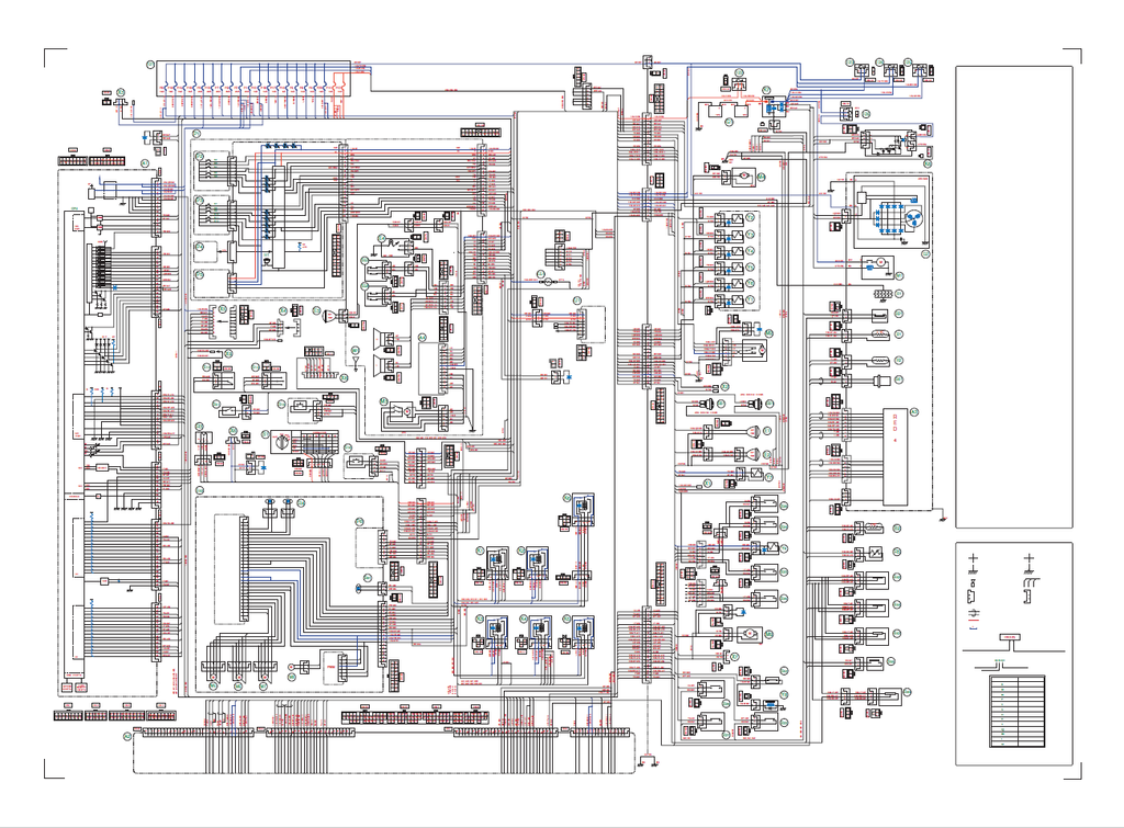
- Physical Fold-Out Schematics Included: Unlike standard digital copies that strip away physical pocket inserts, this specific file fully incorporates the original "Large format hydraulic and electrical schematics" (OEM Reference 9-36070GB) at the very end of the manual, ensuring 100% unbroken end-to-end circuit tracing.
- Dedicated Engine Block Focus: Following the manufacturer’s strict publication division, this manual comprehensively covers engine removal, installation, radiator systems, and external ECM diagnostics. However, deep internal mechanical teardowns of the diesel engine block are explicitly redirected to a separate, dedicated Engine Service Manual.
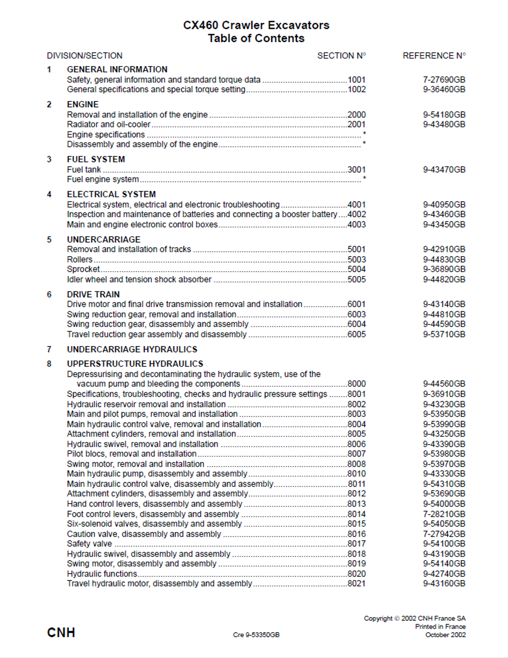
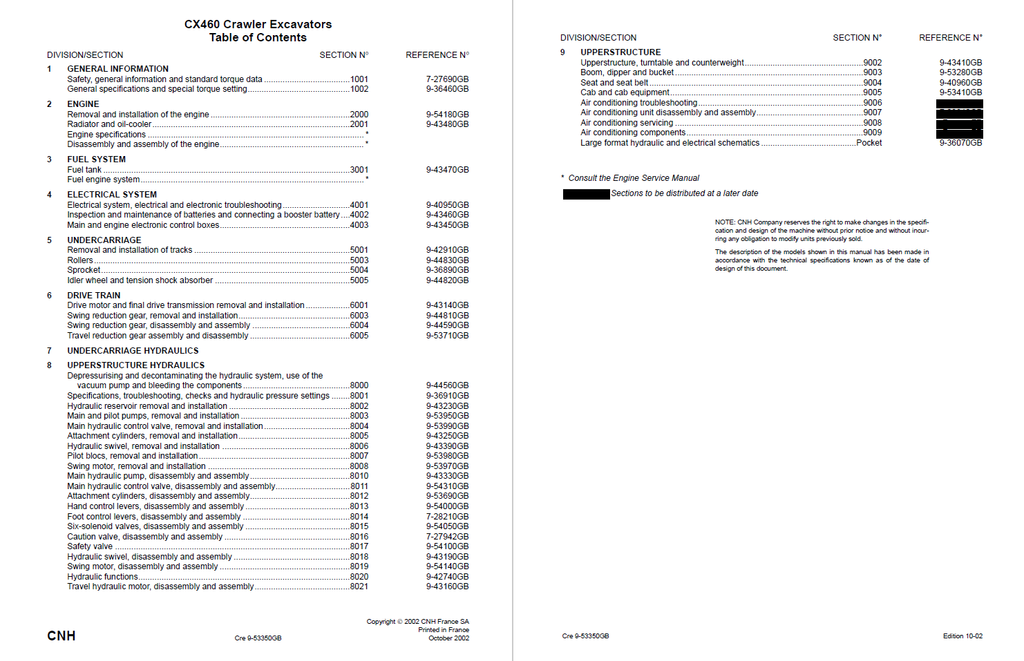
Table of Contents
- GENERAL INFORMATION
- Safety, general information and standard torque data
- General information
- Safety
- Standard torque data for cap screws and nuts
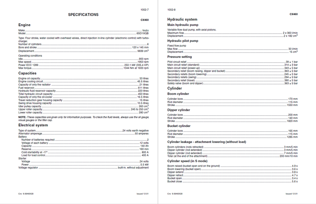
- Specifications
- Safety, general information and standard torque data
- FUEL SYSTEM
- Fuel tank
- ELECTRICAL SYSTEM
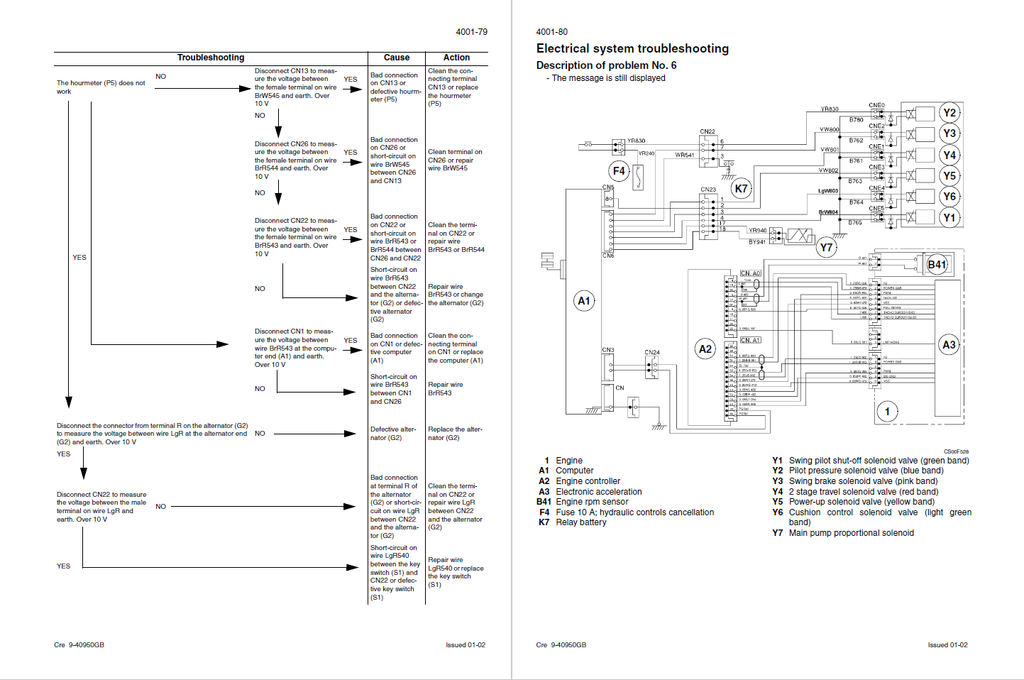
- Electrical system, electrical and electronic troubleshooting
- Special tools
- Operating principles
- Engine checks
- Work mode selection
- H/S/L mode checking
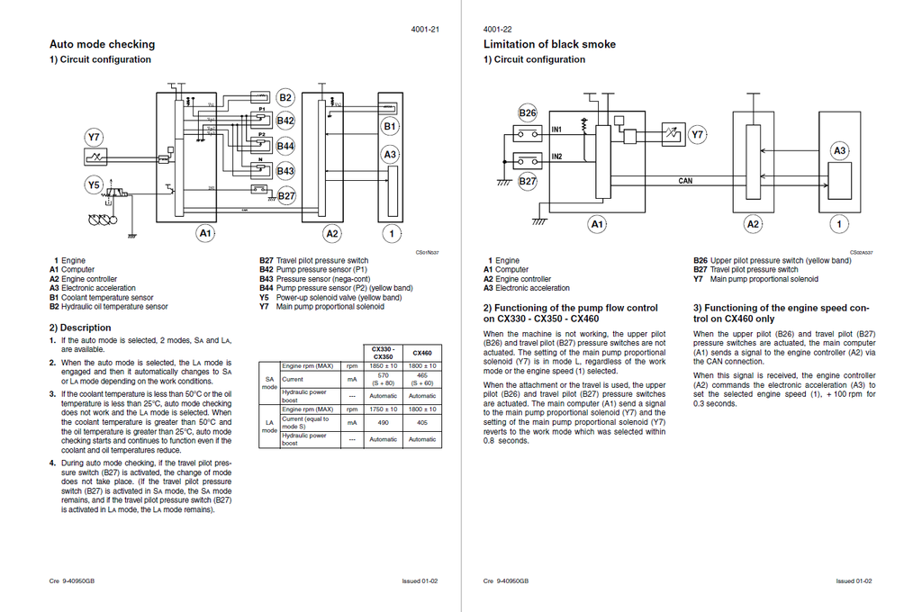
- Auto mode checking
- Limitation of black smoke
- Engine idle checking (automatic/manual)
- Breaker mode checking
- Acceleration checking
- Automatic engine preheat
- Auto engine warm-up
- Idle checking using the battery voltage and the coolant temperature
- Engine emergency stop
- Back-up mode
- Function locking
- Protection by power transistor
- Coolant temperature indicator
- Hydraulic oil temperature indicator
- Fuel level
- Access to monitor displays
- Machine condition
- Diagnostic code
- Machine history
- Re-initialisation
- Warning messages
- Message display
- Excavator model selection procedure
- Changing the language code
- Changing the access code for the anti-theft system
- Troubleshooting
- Prior inspections
- Reading the organisation charts
- Procedures
- Electrical inspection of components
- Inspection equipment
- Proportional solenoid
- Engine emergency stop motor
- 6 solenoid valve bank
- Inspection and maintenance of batteries and connecting a booster battery
- Specifications
- Maintenance
- Electrolyte level
- Main and engine electronic control boxes
- Electrical system, electrical and electronic troubleshooting
- UNDERCARRIAGE
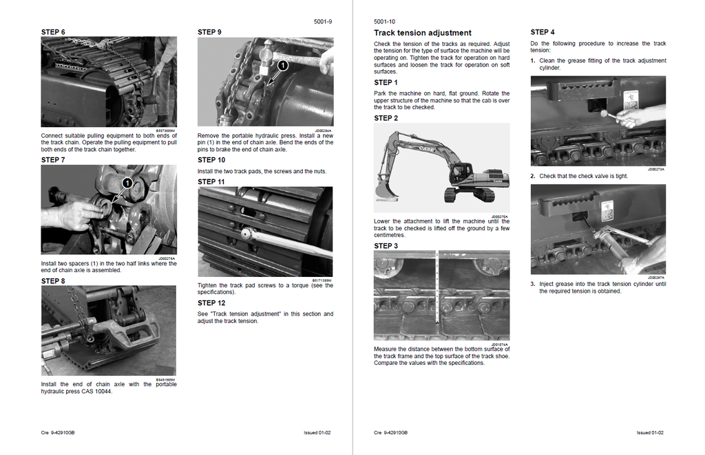
- Removal and installation of the tracks set
- Specifications
- Special torque settings
- Special tools
- Tracks set
- Description
- Removal
- Reconditioning
- Disassembly
- Inspection
- Assembly
- Installation
- Lower roller
- Description
- Removal
- Reconditioning
- Disassembly
- Inspection
- Assembly
- Installation
- Upper roller
- Description
- Removal
- Reconditioning
- Disassembly
- Inspection
- Assembly
- Installation
- Removal and installation of the tracks set
- DRIVE TRAIN
- Removal and installation of the travel-motor reduction gear assembly
- Specifications
- Special torque settings
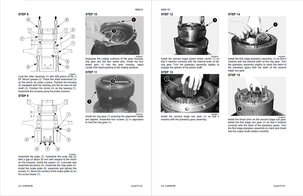
- Swing reduction gear
- Description
- Disassembly
- Inspection
- Assembly
- Removal and installation of the travel-motor reduction gear assembly
- UPPERSTRUCTURE HYDRAULICS
- Pressure release and decontamination of the hydraulic system, use of the vacuum pump and bleeding the components
- Vacuum pump
- Installation
- Removal
- Bleeding air from the main hydraulic system components
- Decontaminating the hydraulic circuit
- Vacuum pump
- Specifications, troubleshooting, checks and hydraulic pressure settings
- Specifications
- Special tools
- Identification of hydraulic components
- Pump
- Control valve
- 6 solenoid valve row
- Preparation before inspection
- Releasing pressure in the hydraulic system
- Installing the pilot pressure test point
- Installing the flowmeter (Checking hydraulic pump flows)
- Main pilot system relief (H) test
- Checking travel drift
- Checking for leaks on the travel motor
- Checking the swing motor for leaks
- Troubleshooting
- Hydraulic reservoir removal and installation
- Main and pilot pumps, removal and installation
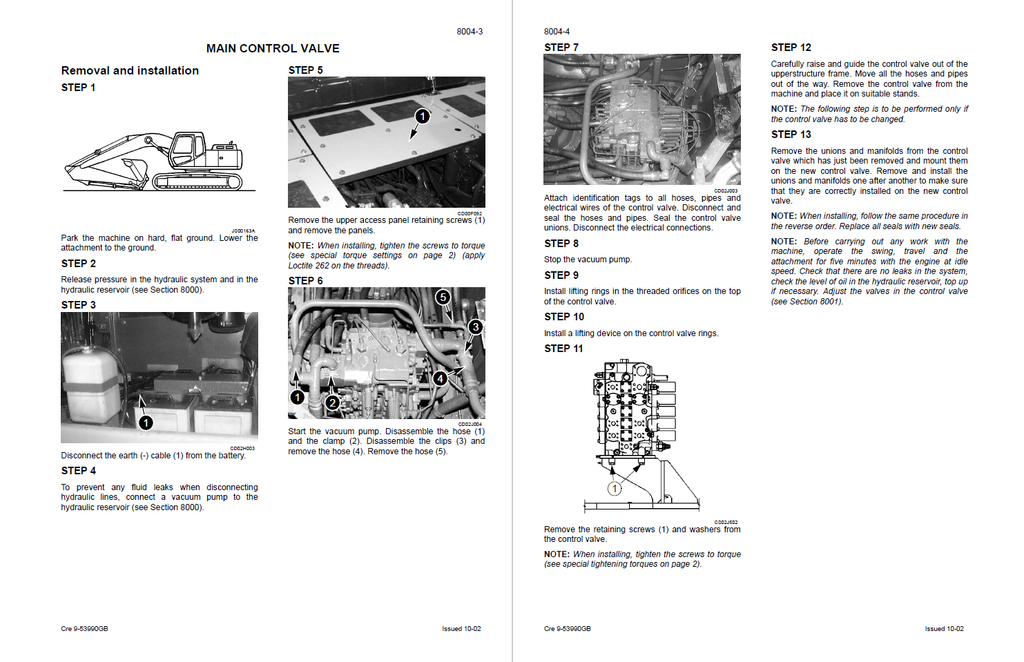
- Main hydraulic control valve, removal and installation
- Attachment cylinders, removal and installation
- Hydraulic swivel, removal and installation
- Pilot blocs, removal and installation
- Pilot function blocks
- Travel pedal block
- LH control lever
- RH control lever
- Swing shuttle block
- Cushion control valve
- Servo control and return manifold block
- 6 solenoid valve block
- Pilot function blocks
- Swing motor, removal and installation
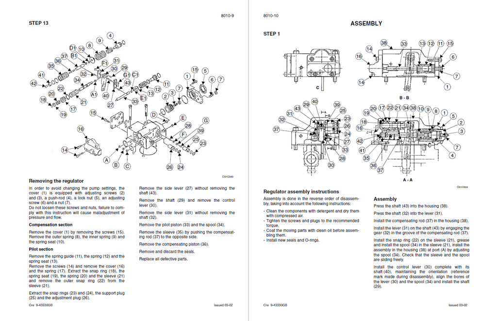
- Main hydraulic pump, disassembly and assembly
- Identifying the components
- Description
- Disassembly
- Assembly
- Identifying the components
- Main hydraulic control valve, disassembly and assembly
- Specifications
- Tools required
- Special torque settings
- Control valve
- Description
- Identifying the ports
- Disassembly
- General instructions
- Auxiliary assembly
- Plug assembly
- Cleaning
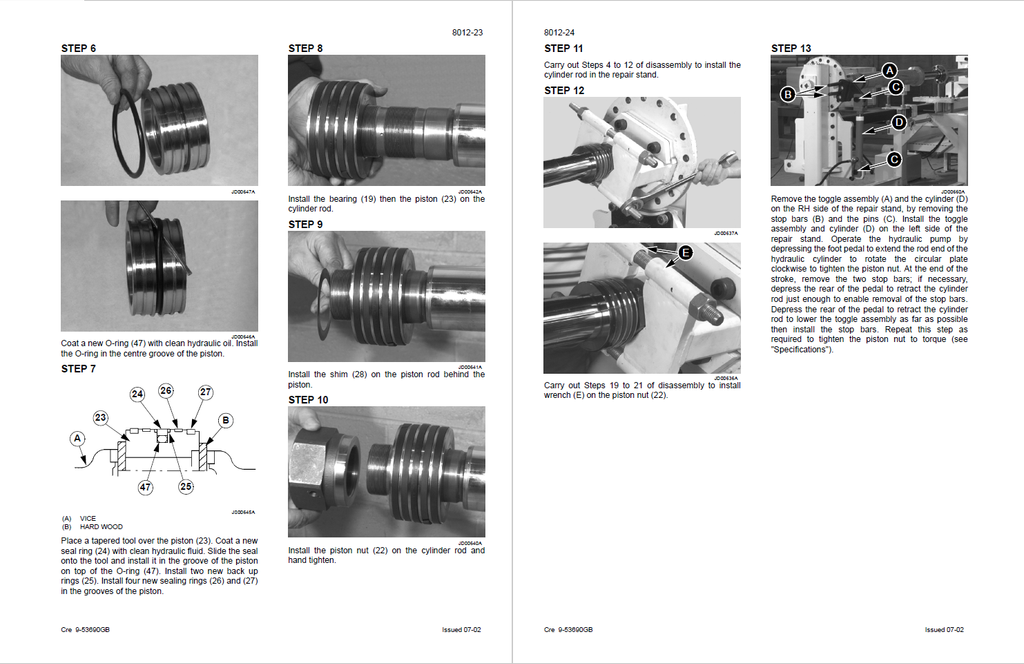
- Attachment cylinders, disassembly and assembly
- Special tools
- Cylinders
- Boom cylinder description
- Cleaning the components
- Inspection
- Hand control levers, disassembly and assembly
- Assembly
- Foot control levers, disassembly and assembly
- Disassembly
- Six-solenoid valves, disassembly and assembly
- Specifications
- Six solenoid valves block
- Identifying the ports and the solenoid valves
- Cross-sectional view
- Disassembly and assembly
- Inspection
- Caution valve, disassembly and assembly
- Safety valve
- Hydraulic swivel, disassembly and assembly
- Swing motor, disassembly and assembly
- Disassembly
- Hydraulic functions
- List of functions
- Controls in neutral position
- Travel high speed circuit
- Low speed travel circuit
- Straight-line travel circuit
- Swing circuit
- Swing variable priority circuit
- Boom raising circuit
- Boom lowering, load holding circuit
- Boom lowering additional flow circuit
- Boom lowering anti-vibration circuit
- Dipper extending, load holding valve circuit
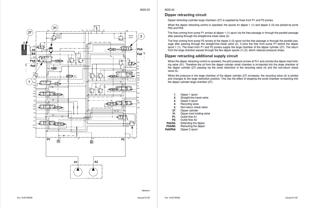
- Dipper retracting circuit
- Dipper retracting additional supply circuit
- Bucket opening circuit
- Bucket closing circuit
- Crusher circuit
- Breaker circuit
- Travel hydraulic motor, disassembly and assembly
- Travel motor
- Description
- Disassembly
- Assembly
- Inspection
- Travel motor
- Pressure release and decontamination of the hydraulic system, use of the vacuum pump and bleeding the components
- UPPERSTRUCTURE
- Upperstructure, turntable and counterweight
- Boom, dipper and bucket
- Dipper
- Description
- Removal
- Installation
- Boom
- Description
- Removal
- Installation
- Dipper
- Seat and seat belt
- Specifications
- Safety belt
- Removal
- Repose
- Cab and cab equipment
- Specification
- Special torque settings
- Cab
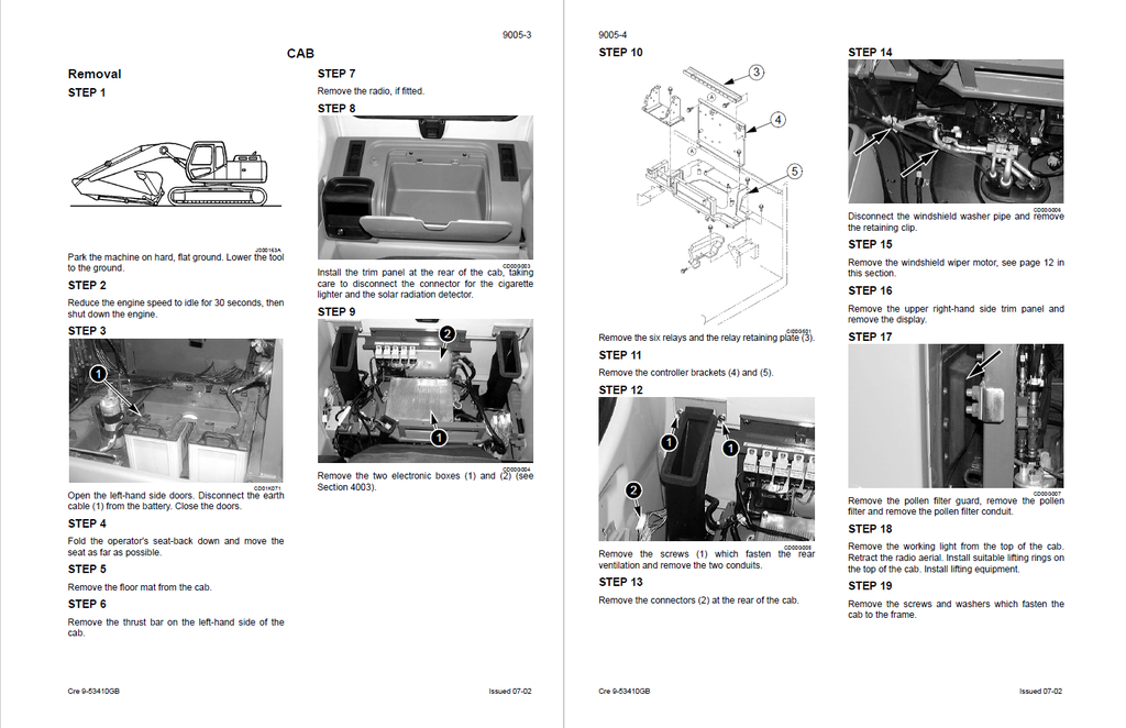
- Removal
- Installation
- Air conditioning unit disassembly and assembly
- Large format hydraulic and electrical schematics