

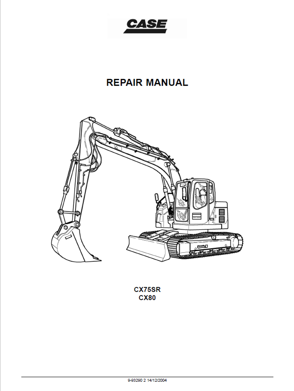
CASE Construction CX75SR, CX80 Crawler Excavator Service Manual 9-93290NA English
Official Manual Overview
Arm your workshop with the definitive OEM Repair Manual engineered exclusively for the CASE CX75SR and CX80 Crawler Excavators. Designed for master technicians, this master blueprint delivers dealership-level teardown and calibration protocols for the machine's core hydraulic, structural, and travel systems. It provides exhaustive overhaul data for both monobloc and offset boom configurations across North American (NA) and European (WE) models. The guide dictates absolute mechanical certainty, enforcing massive tightening specifications (such as 850–992 Nm for the counterweight and 521–608 Nm for the lower rollers) alongside micro-tolerance wear limits for the steel/rubber track tensioning mechanisms and swing reduction gears.
Important Notice: This volume integrates comprehensive large-format hydraulic and electrical schematics, but explicitly directs technicians to consult the independent "Engine Service Manual" for deep internal block reconstruction of the Isuzu CC-4JG1 diesel engine.
- Brands: CASE Construction
- Equipment Type: Crawler Excavator
- Manuals Type: Service Manual
- Machine Model: CX75SR, CX80
- Serial Number: N/R
- Region: North America, Europe
- Book Code: 9-93290NA
- Issued: Printed in France - December 2004
- Language: English
- Pages: 862
- File Format: PDF (Searchable)
Core Selling Points
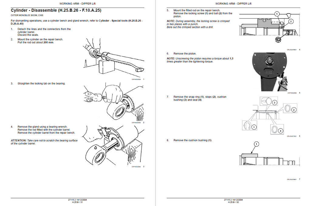
- Extreme Hydraulic Cylinder Teardown: Never compromise on structural lifting safety. This master manual delivers dealership-level disassembly protocols for all heavy-duty hydraulic actuators. It mandates uncompromising tightening specifications, instructing mechanics to lock the boom cylinder piston nut at an immense 3000 Nm, torque the gland assembly to 834 Nm, and strictly utilize the 380000812 repair bench alongside the OEM6203 gland wrench for safe resealing.
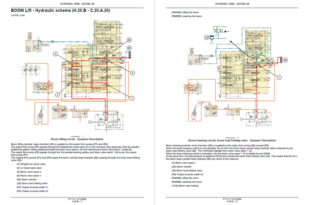
- Dynamic Fluid Power Calibration: Restore absolute breakout force to your crawler. The guide maps out exact hydrostatic benchmarking criteria, requiring technicians to calibrate the main relief valve to a strict 31.4 MPa (4554 psi), set the secondary relief valves exactly to 31.9 MPa (4627 psi), and lock the pilot pressure circuit at 4.2 MPa (609 psi).
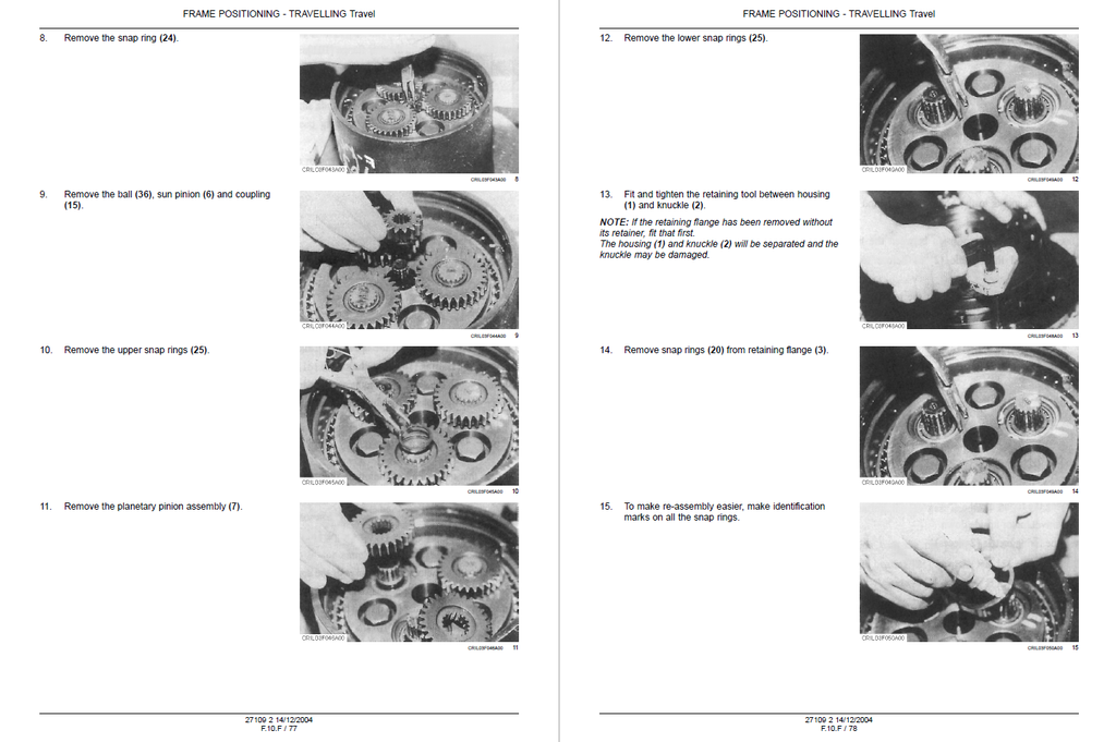
- Micro-Tolerance Motor & Reducer Overhaul: Evaluate planetary final drives and travel motors with scientific precision. The text provides step-by-step disassembly charts for the spur gear reducers and strictly regulates internal wear limits—condemning the hydraulic motor immediately if the axial clearance between the piston and shoe exceeds 0.14 mm (against a new factory tolerance of 0.04 mm), or if the swing brake fails to hold at a 97.1 Nm torque load.
Features & Highlights
- High-Definition Electrical Topologies: Master the machine's complex nervous system. The documentation integrates intricate circuit timing diagrams and harness layouts, detailing the precise usage of the proprietary CAS-30039 test electrical connector kit. It empowers technicians to physically trace sensor continuity, such as verifying the B11 coolant temperature thermo-switch closes at exactly 110°C and opens at 103°C.
- Comprehensive Structural Metrology: Navigate chassis and boom linkage repairs with absolute dimensional accuracy. The manual provides an exhaustive wear matrix for all articulation points, demanding the replacement of the boom foot pin if the diameter wears down to 59 mm, and condemning the bushing if the bore expands past the 61.5 mm service limit.
- Proprietary Tooling Registries: Equip your shop with the exact parameters needed for dealership-level intervention. The text eliminates diagnostic guesswork by mapping out all specialized service tools, including the CAS-1559 digital multimeter for CAN network tracing and locally fabricated 150 mm diameter pump brackets for upright hydraulic pump reconstruction.
Problem Solver
- Defeating Hydrostatic Degradation: Stop blindly replacing expensive control valves. The diagnostic flowcharts empower technicians to systematically trace pressure drops and erratic machine behavior. If the working pressure is incorrect, the logic trees guide you to inspect the main relief valve seat for contamination or readjust the locking nut, preventing unnecessary total component replacements.
- Eradicating Elusive Phantom Faults: Transform erratic electrical drops into calculated repair sequences. Using the electronic timing diagrams, mechanics can evaluate the exact millisecond signal response of the B21 engine oil pressure switch (verifying it opens at exactly 0.3 MPa) or track voltage drops across the B27 travel pilot pressure switch, curing false dashboard alarms.
- Resolves Severe Undercarriage Binding: Navigate crawler tensioning and track failures scientifically. By referencing the detailed service limit tables, technicians can accurately evaluate the drive sprocket pitch, idler wheel diameter, and lower roller leakage, pinpointing specific undercarriage weaknesses before a catastrophic track derailment occurs.
Important Pre-Purchase Advisories
- Engine Maintenance Notice: While this Repair Manual provides instructions for engine removal, installation, and external systems (cooling, fuel, starting), it explicitly directs technicians to consult the independent "Engine Service Manual (CC-4JG1)" for deep internal engine block overhauls.
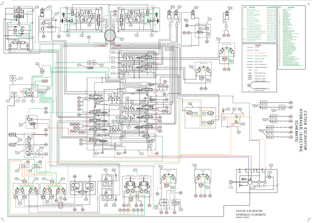
- Integrated Large-Format Schematics: The highly detailed, large-format hydraulic and electrical circuit diagrams (originally designated as print number 9-43610) are fully embedded and consolidated within the final pages of this digital volume for complete system tracing.
Table of Contents
- INTRODUCTION
- Foreword
- Safety rules
- Basic instructions
- Torque
- Dimension
- Weight
- Consumables
- Hydraulic contamination
- Product identification
- DISTRIBUTION SYSTEMS
- PRIMARY HYDRAULIC POWER SYSTEM
- TECHNICAL DATA
- PRIMARY HYDRAULIC POWER SYSTEM - General specification
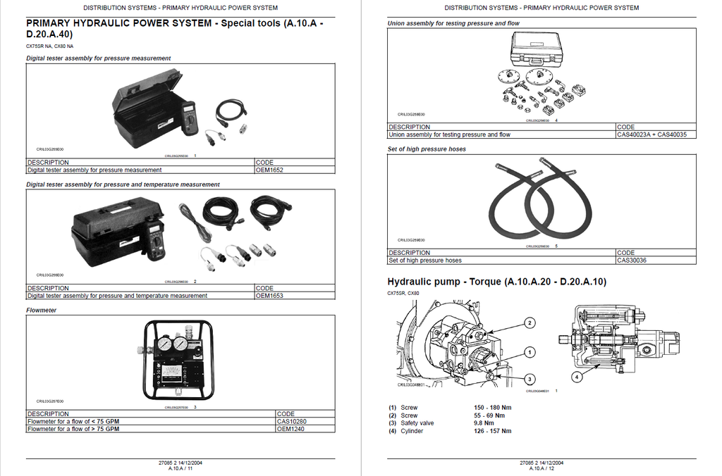
- PRIMARY HYDRAULIC POWER SYSTEM - Special tools
- Hydraulic pump - Torque
- Hydraulic pump - Special tools
- Stack valve Inlet section - Torque
- Stack valve Outlet section - Torque
- FUNCTIONAL DATA
- PRIMARY HYDRAULIC POWER SYSTEM - Static description
- PRIMARY HYDRAULIC POWER SYSTEM - Dynamic description
- Hydraulic pump - External view
- Hydraulic pump - Sectional view
- Stack valve - External view
- Stack valve - Sectional view
- Stack valve Inlet section - Sectional view
- Stack valve Outlet section - Sectional view
- Sensing system Temperature sensor - Electronic schema
- SERVICE
- PRIMARY HYDRAULIC POWER SYSTEM - Warm up
- PRIMARY HYDRAULIC POWER SYSTEM - Depressurising
- PRIMARY HYDRAULIC POWER SYSTEM - Drain fluid
- PRIMARY HYDRAULIC POWER SYSTEM - Bleed
- PRIMARY HYDRAULIC POWER SYSTEM - Decontaminating
- Hydraulic pump - Remove
- Hydraulic pump - Disassemble
- Hydraulic pump - Assemble
- Hydraulic pump - Install
- Hydraulic pump - Bleed
- Reservoir - Remove
- Reservoir - Install
- Oil filter - Remove
- Oil filter - Install
- Stack valve - Remove
- Stack valve Inlet section - Disassemble
- Stack valve Outlet section - Disassemble
- Stack valve - Visual inspection
- Stack valve Inlet section - Assemble
- Stack valve Outlet section - Assemble
- Stack valve - Install
- Relief valve - Disassemble
- Relief valve - Assemble
- Relief valve - Pressure setting
- Sensing system Temperature sensor - Electrical test
- DIAGNOSTIC
- PRIMARY HYDRAULIC POWER SYSTEM - Troubleshooting
- Stack valve - Troubleshooting
- Relief valve - Troubleshooting
- TECHNICAL DATA
- SECONDARY HYDRAULIC POWER SYSTEM
- FUNCTIONAL DATA
- Stack valve Inlet section - Sectional view
- Stack valve Outlet section - Sectional view
- SERVICE
- Hydraulic pump - Remove
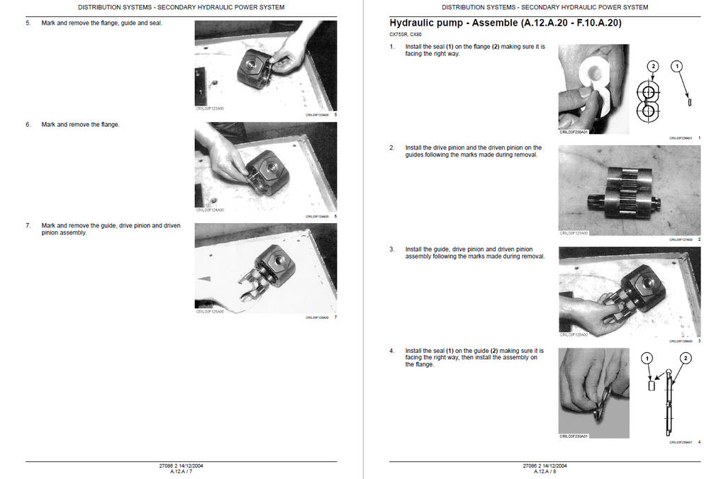
- Hydraulic pump - Disassemble
- Hydraulic pump - Assemble
- Hydraulic pump - Install
- Stack valve - Disassemble
- Stack valve Inlet section - Disassemble
- Stack valve Inlet section - Assemble
- Stack valve - Assemble
- Relief valve - Disassemble
- Relief valve - Assemble
- Relief valve - Pressure setting
- FUNCTIONAL DATA
- HYDRAULIC COMMAND SYSTEM
- SERVICE
- Hydraulic pump - Remove
- Hydraulic pump - Disassemble
- Hydraulic pump - Assemble
- Hydraulic pump - Install
- Relief valve - Pressure setting
- Accumulator - Check
- DIAGNOSTIC
- HYDRAULIC COMMAND SYSTEM - Troubleshooting
- SERVICE
- ELECTRICAL POWER SYSTEM
- TECHNICAL DATA
- ELECTRICAL POWER SYSTEM - General specification
- ELECTRICAL POWER SYSTEM - Special tools
- Battery - General specification
- FUNCTIONAL DATA
- ELECTRICAL POWER SYSTEM - Static description
- ELECTRICAL POWER SYSTEM - Overview
- Fuse and relay box - Overview
- Fuse and relay box - Detailed view
- Alternator - Electronic schema
- Circuit breaker - Electronic schema
- SERVICE
- Battery - Visual inspection
- Battery - Disconnect
- Battery - Remove
- Battery - Check
- Battery - Charging
- Battery - Overhaul
- Battery - Install
- Battery - Connect
- Alternator - Tension adjust
- TECHNICAL DATA
- LIGHTING SYSTEM
- FUNCTIONAL DATA
- Front work light - Electronic schema
- FUNCTIONAL DATA
- PRIMARY HYDRAULIC POWER SYSTEM
- POWER PRODUCTION
- ENGINE
- TECHNICAL DATA
- ENGINE - General specification
- SERVICE
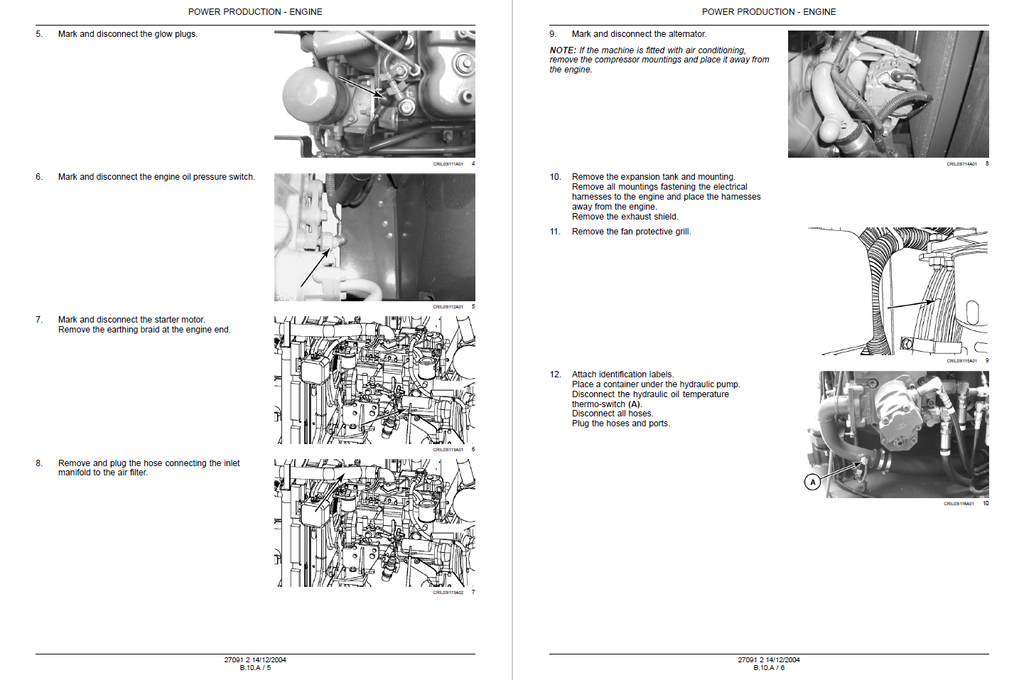
- ENGINE - Remove
- ENGINE - Install
- TECHNICAL DATA
- FUEL AND INJECTION SYSTEM
- FUNCTIONAL DATA
- Throttle command Electronic throttle - Electronic schema
- Fuel shut-off Electrical shut-off - Electronic schema
- Sensing system Level sensor - Electronic schema
- SERVICE
- Fuel tank - Remove
- Fuel tank - Install
- Fuel filter system Sediment filter - Remove
- Fuel filter system Sediment filter - Cleaning
- FUNCTIONAL DATA
- AIR INTAKE SYSTEM
- SERVICE
- Air cleaner - Install
- Air cleaner - Remove
- SERVICE
- EXHAUST SYSTEM
- SERVICE
- Silencer - Install
- Silencer - Remove
- SERVICE
- ENGINE COOLANT SYSTEM
- FUNCTIONAL DATA
- Sensing system Coolant temperature - Electronic schema
- SERVICE
- ENGINE COOLANT SYSTEM - Drain fluid
- ENGINE COOLANT SYSTEM - Interior washing
- ENGINE COOLANT SYSTEM - Filling
- Radiator - Remove
- Radiator - Install
- Radiator - Exterior washing
- Sensing system Coolant temperature - Electrical test
- FUNCTIONAL DATA
- LUBRICATION SYSTEM
- FUNCTIONAL DATA
- Sensing system Oil pressure - Electronic schema
- FUNCTIONAL DATA
- STARTING SYSTEM
- TECHNICAL DATA
- Engine starter - General specification
- FUNCTIONAL DATA
- Start control - Electronic schema
- TECHNICAL DATA
- PTO POWER IN
- FUNCTIONAL DATA
- Drive system - Overview
- SERVICE
- Drive system - Remove
- Drive system - Install
- FUNCTIONAL DATA
- ENGINE
- TRAVELLING
- WHEELS AND TRACKS Tracks
- TECHNICAL DATA
- Drive sprocket - Special tools
- Drive sprocket - Service limits
- Steel track - Service limits
- Roller Lower roller - Special tools
- Roller Lower roller - Service limits
- Roller Upper roller - Service limits
- Idler wheel - Special tools
- Idler wheel - Service limits
- FUNCTIONAL DATA
- Steel track - Exploded view
- Track tensioning mechanism Shock absorber - Exploded view
- Track tensioning mechanism Adjuster-recoil mechanism - Exploded view
- Roller Lower roller - Sectional view
- Roller Upper roller - Sectional view
- SERVICE
- Drive sprocket - Remove
- Drive sprocket - Install
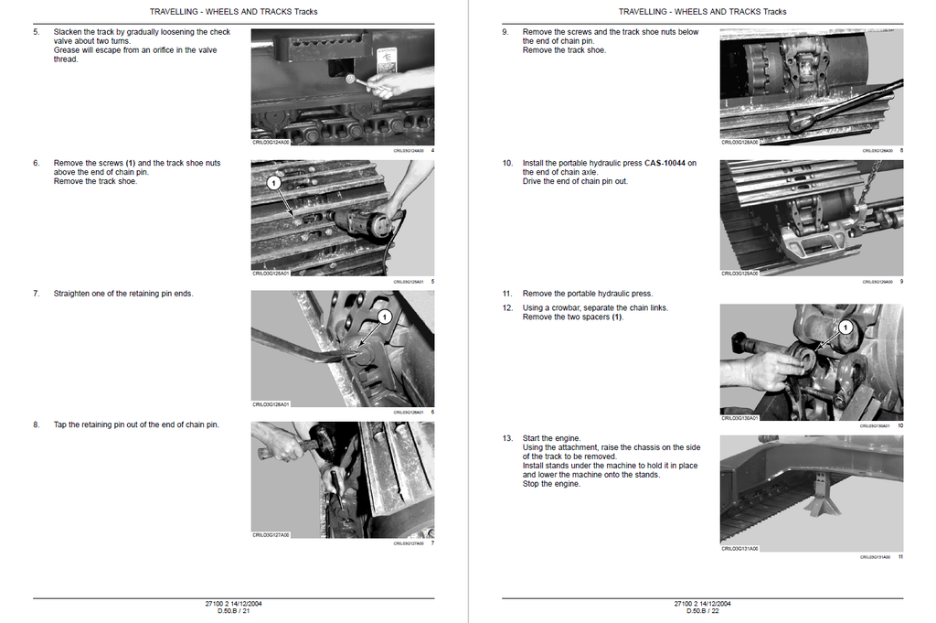
- Steel track - Remove
- Steel track Chain - Measure
- Steel track - Install
- Rubber track - Visual inspection
- Rubber track - Remove
- Rubber track - Install
- Track tensioning mechanism - Tension adjust
- Track tensioning mechanism Shock absorber - Remove
- Track tensioning mechanism Shock absorber - Disassemble
- Track tensioning mechanism Shock absorber - Assemble
- Track tensioning mechanism Shock absorber - Install
- Track tensioning mechanism Adjuster-recoil mechanism - Remove
- Track tensioning mechanism Adjuster-recoil mechanism - Disassemble
- Track tensioning mechanism Adjuster-recoil mechanism - Assemble
- Track tensioning mechanism Adjuster-recoil mechanism - Install
- Roller - Leakage test
- Roller Lower roller - Remove
- Roller Lower roller - Disassemble
- Roller Lower roller - Visual inspection
- Roller Lower roller - Assemble
- Roller Lower roller - Install
- Roller Upper roller - Remove
- Roller Upper roller - Disassemble
- Roller Upper roller - Visual inspection
- Roller Upper roller - Assemble
- Roller Upper roller - Install
- Idler wheel - Disassemble
- Idler wheel - Assemble
- TECHNICAL DATA
- WHEELS AND TRACKS Tracks
- BODY AND STRUCTURE
- SHIELD
- SERVICE
- Side shield - Remove
- Upper shield - Remove
- Engine hood - Remove
- Protective shield Guard - Remove
- SERVICE
- USER CONTROLS AND SEAT
- FUNCTIONAL DATA
- Instrument panel - Detailed view
- FUNCTIONAL DATA
- USER PLATFORM
- FUNCTIONAL DATA
- Wiper system - Electronic schema
- Windscreen washer system - Electronic schema
- FUNCTIONAL DATA
- ENVIRONMENT CONTROL Heating, ventilation and air-conditioning
- TECHNICAL DATA
- ENVIRONMENT CONTROL Heating, ventilation and air-conditioning - Special tools
- FUNCTIONAL DATA
- ENVIRONMENT CONTROL Heating, ventilation and air-conditioning - Dynamic description
- Command - Overview
- Electronic HVAC control - Electrical schema
- SERVICE
- ENVIRONMENT CONTROL Heating, ventilation and air-conditioning - Evacuate
- ENVIRONMENT CONTROL Heating, ventilation and air-conditioning - Disassemble
- ENVIRONMENT CONTROL Heating, ventilation and air-conditioning - Charging
- Compressor - Remove
- Compressor - Install
- Receiver/drier - Remove
- Receiver/drier - Install
- Condenser - Remove
- Condenser - Install
- DIAGNOSTIC
- ENVIRONMENT CONTROL Heating, ventilation and air-conditioning - Troubleshooting
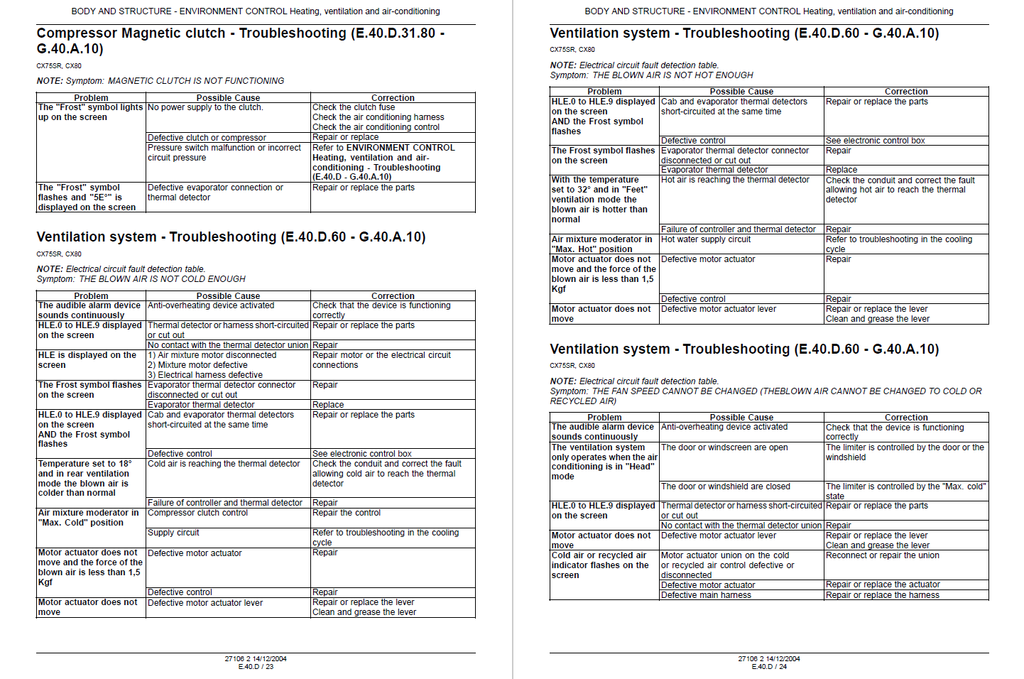
- Compressor Magnetic clutch - Troubleshooting
- Ventilation system - Troubleshooting
- TECHNICAL DATA
- SAFETY SECURITY ACCESSORIES Safety
- FUNCTIONAL DATA
- Hydraulic lock-out - Electrical schema
- Hydraulic lock-out Electrovalve - External view
- Hydraulic lock-out Electrovalve - Sectional view
- SERVICE
- Hydraulic lock-out Electrovalve - Electrical test
- Hydraulic lock-out Electrovalve - Remove
- Hydraulic lock-out Electrovalve - Disassemble
- Hydraulic lock-out Electrovalve - Visual inspection
- Hydraulic lock-out Electrovalve - Assemble
- Hydraulic lock-out Electrovalve - Install
- FUNCTIONAL DATA
- SHIELD
- FRAME POSITIONING
- TRAVELLING Travel
- TECHNICAL DATA
- Command valve Foot command valve - General specification
- Control valve - Torque
- Hydraulic motor - Torque
- Hydraulic motor - Special tools
- Reducer, spur gear - Special tools
- FUNCTIONAL DATA
- TRAVELLING Travel - Electronic schema
- TRAVELLING Travel - Hydraulic schema
- Command valve Foot command valve - Sectional view
- Command valve Speed selection valve - Overview
- Control valve - Sectional view
- Hydraulic motor - Exploded view
- Hydraulic motor - Sectional view
- Reducer, spur gear - Exploded view
- Reducer, spur gear - Sectional view
- Sensing system Alarm - Electronic schema
- SERVICE
- Command valve Foot command valve - Remove
- Command valve Foot command valve - Disassemble
- Command valve Foot command valve - Visual inspection
- Command valve Foot command valve - Assemble
- Command valve Foot command valve - Install
- Command valve Speed selection valve - Electrical test
- Command valve Speed selection valve - Overhaul
- Control valve - Disassemble
- Control valve - Assemble
- Hydraulic motor - Remove
- Hydraulic motor - Disassemble
- Hydraulic motor - Check
- Hydraulic motor - Assemble
- Hydraulic motor - Install
- Hydraulic motor - Leakage test
- Relief valve - Pressure test
- Relief valve - Pressure setting
- Reducer, spur gear - Remove
- Reducer, spur gear - Disassemble
- Reducer, spur gear - Visual inspection
- Reducer, spur gear - Measure
- Reducer, spur gear Bearing - Preload
- Reducer, spur gear - Assemble
- Reducer, spur gear - Install
- DIAGNOSTIC
- TRAVELLING Travel - Troubleshooting
- Command valve Foot command valve - Troubleshooting
- TECHNICAL DATA
- STABILISING Ballasting
- FUNCTIONAL DATA
- Rear ballasting - Overview
- SERVICE
- Rear ballasting - Remove
- Rear ballasting - Install
- FUNCTIONAL DATA
- SWINGING Circular swing
- TECHNICAL DATA
- Command valve Hand command valve - Torque
- Hydraulic motor - Special tools
- Reducer, spur gear - General specification
- Reducer, spur gear - Special tools
- Swivel - General specification
- FUNCTIONAL DATA
- SWINGING Circular swing - Hydraulic schema
- Command valve Cushion valve - External view
- Command valve Cushion valve - Sectional view
- Command valve Hand command valve - Sectional view
- Control valve - Sectional view
- Lock-out valve - Exploded view
- Lock-out valve - Sectional view
- Hydraulic motor - Exploded view
- Hydraulic motor - Sectional view
- Reducer, spur gear - Exploded view
- Reducer, spur gear - Sectional view
- Hydraulic brake - Electronic schema
- Hydraulic brake Electrovalve - Overview
- Swivel - Exploded view
- SERVICE
- Command valve Cushion valve - Remove
- Command valve Cushion valve - Disassemble
- Command valve Cushion valve - Assemble
- Command valve Cushion valve - Install
- Command valve Hand command valve - Remove
- Command valve Hand command valve - Disassemble
- Command valve Hand command valve - Cleaning
- Command valve Hand command valve - Visual inspection
- Command valve Hand command valve - Assemble
- Command valve Hand command valve - Install
- Control valve - Disassemble
- Control valve - Assemble
- Lock-out valve - Remove
- Lock-out valve - Disassemble
- Lock-out valve - Assemble
- Lock-out valve - Install
- Hydraulic motor - Remove
- Hydraulic motor - Disassemble
- Hydraulic motor - Visual inspection
- Hydraulic motor - Assemble
- Hydraulic motor - Install
- Hydraulic motor - Bleed
- Hydraulic motor - Leakage test
- Relief valve - Pressure test
- Relief valve - Pressure setting
- Reducer, spur gear - Remove
- Reducer, spur gear - Disassemble
- Reducer, spur gear - Visual inspection
- Reducer, spur gear - Assemble
- Reducer, spur gear - Install
- Bearing and ring gear - Check
- Bearing and ring gear - Remove
- Bearing and ring gear - Install
- Hydraulic brake - Pressure test
- Hydraulic brake Electrovalve - Electrical test
- Hydraulic brake Electrovalve - Overhaul
- Swivel - Remove
- Swivel - Disassemble
- Swivel - Cleaning
- Swivel - Assemble
- Swivel - Install
- DIAGNOSTIC
- SWINGING Circular swing - Troubleshooting
- TECHNICAL DATA
- TRAVELLING Travel
- WORKING ARM
- BOOM Lift
- TECHNICAL DATA
- BOOM Lift - Service limits
- Command valve Hand control valve - Torque
- Control valve - Torque
- Cylinder - Special tools
- Cylinder - Torque
- FUNCTIONAL DATA
- BOOM Lift - Hydraulic schema
- Command valve Cushion valve - External view
- Command valve Cushion valve - Sectional view
- Command valve Hand control valve - Sectional view
- Control valve - Sectional view
- Cylinder - Sectional view
- Arm - Exploded view
- Sensing system - Electronic schema
- SERVICE
- Command valve Cushion valve - Remove
- Command valve Cushion valve - Install
- Command valve Hand control valve - Overhaul
- Control valve - Disassemble
- Control valve - Assemble
- Load holding valve - Disassemble
- Load holding valve - Assemble
- Relief valve - Disassemble
- Relief valve - Assemble
- Relief valve - Pressure test
- Relief valve - Pressure setting
- Cylinder - Remove
- Cylinder - Disassemble
- Cylinder - Visual inspection
- Cylinder - Assemble
- Cylinder - Install
- Arm - Remove
- Arm - Install
- Safety valve - Remove
- Safety valve - Install
- Safety valve - Pressure setting
- TECHNICAL DATA
- BOOM Swing
- TECHNICAL DATA
- BOOM Swing - Service limits
- Control valve - Torque
- Cylinder - Torque
- FUNCTIONAL DATA
- BOOM Swing - Hydraulic schema
- Control valve - Sectional view
- Cylinder - Sectional view
- SERVICE
- Command valve Foot command valve - Remove
- Command valve Foot command valve - Install
- Command valve Foot command valve - Overhaul
- Control valve - Disassemble
- Control valve - Assemble
- Relief valve - Disassemble
- Relief valve - Assemble
- Relief valve - Pressure test
- Relief valve - Pressure setting
- Cylinder - Remove
- Cylinder - Disassemble
- Cylinder - Assemble
- Cylinder - Install
- TECHNICAL DATA
- DIPPER Lift
- TECHNICAL DATA
- DIPPER Lift - Service limits
- Command valve Hand control valve - Torque
- Control valve - Torque
- Cylinder - Torque
- FUNCTIONAL DATA
- DIPPER Lift - Hydraulic schema
- Command valve Hand control valve - Sectional view
- Control valve - Sectional view
- Cylinder - Sectional view
- Arm - Exploded view
- SERVICE
- Command valve Hand control valve - Overhaul
- Control valve - Disassemble
- Control valve - Assemble
- Relief valve - Disassemble
- Relief valve - Assemble
- Relief valve - Pressure test
- Relief valve - Pressure setting
- Cylinder - Remove
- Cylinder - Disassemble
- Cylinder - Assemble
- Cylinder - Install
- Arm - Remove
- Arm - Install
- Safety valve - Remove
- Safety valve - Install
- Safety valve - Pressure setting
- TECHNICAL DATA
- ARM TOOL ATTACHMENT Tilt
- TECHNICAL DATA
- ARM TOOL ATTACHMENT Tilt - Service limits
- Command valve Hand control valve - Torque
- Control valve - Torque
- Cylinder - Torque
- FUNCTIONAL DATA
- ARM TOOL ATTACHMENT Tilt - Hydraulic schema
- Command valve Hand control valve - Sectional view
- Control valve - Sectional view
- Cylinder - Sectional view
- Arm - Exploded view
- SERVICE
- Command valve Hand control valve - Overhaul
- Control valve - Disassemble
- Control valve - Assemble
- Relief valve - Disassemble
- Relief valve - Assemble
- Relief valve - Pressure test
- Relief valve - Pressure setting
- Cylinder - Remove
- Cylinder - Disassemble
- Cylinder - Assemble
- Cylinder - Install
- Arm - Remove
- Arm - Install
- TECHNICAL DATA
- BOOM Lift
- TOOLS AND COUPLERS
- DIGGING Hammer
- TECHNICAL DATA
- Control valve - Torque
- FUNCTIONAL DATA
- DIGGING Hammer - Hydraulic schema
- Control valve - Sectional view
- SERVICE
- Command valve Foot command valve - Overhaul
- Control valve - Disassemble
- Control valve - Assemble
- TECHNICAL DATA
- LANDSCAPING Dozer blade
- TECHNICAL DATA
- LANDSCAPING Dozer blade - Service limits
- Control valve - Torque
- Cylinder - Torque
- FUNCTIONAL DATA
- LANDSCAPING Dozer blade - Hydraulic schema
- Control valve - Sectional view
- Cylinder - Sectional view
- SERVICE
- LANDSCAPING Dozer blade - Remove
- LANDSCAPING Dozer blade - Install
- Command valve Foot command valve - Remove
- Command valve Foot command valve - Disassemble
- Command valve Foot command valve - Visual inspection
- Command valve Foot command valve - Assemble
- Command valve Foot command valve - Install
- Control valve - Disassemble
- Control valve - Assemble
- Relief valve - Disassemble
- Relief valve - Assemble
- Relief valve - Pressure test
- Relief valve - Pressure setting
- Cylinder - Remove
- Cylinder - Disassemble
- Cylinder - Assemble
- Cylinder - Install
- DIAGNOSTIC
- Command valve Foot command valve - Troubleshooting
- TECHNICAL DATA
- DIGGING Hammer