

CASE Construction CX800 Crawler Excavator Service Manual 9-40300 English
Official Manual Overview
Command the ultimate heavyweight earthmoving machinery with this definitive OEM Service Manual, engineered explicitly for the colossal CASE CX800 Crawler Excavator. Designed exclusively for elite dealership technicians, this volume bypasses routine upkeep to deliver surgical chassis, undercarriage, and fluid system reconstruction protocols. It provides uncompromising calibration matrices for the massive hydraulic architecture, detailing flow metrology for the 2x514 L/min axial piston main pumps and dictating absolutely staggering fastening specifications—such as the 40,300 Nm torque requirement mandated for the dipper and bucket cylinder piston nuts. Furthermore, it transforms the cabin into an advanced diagnostic command center, mapping out the exact keystrokes required to unlock the hidden CHK1 and DIAG engineering screens for deep CAN-bus, proportional solenoid, and electronic regulator troubleshooting. Please note: In strict adherence to CASE's publication strategy, while complete engine removal/installation and ECM diagnostics are exhaustively covered, deep internal block teardowns for the 15.6L Isuzu BB-6WG1XQB diesel engine are explicitly redirected to a dedicated engine manual.
- Brands: CASE Construction
- Equipment Type: Crawler Excavator
- Manuals Type: Service Manual
- Machine Model: CX800
- Serial Number: N/R
- Region: N/R
- Book Code: 9-40300
- Issued: Printed in France, February 2002
- Language: English
- Pages: 618
- File Format: PDF (Searchable)
Core Selling Points
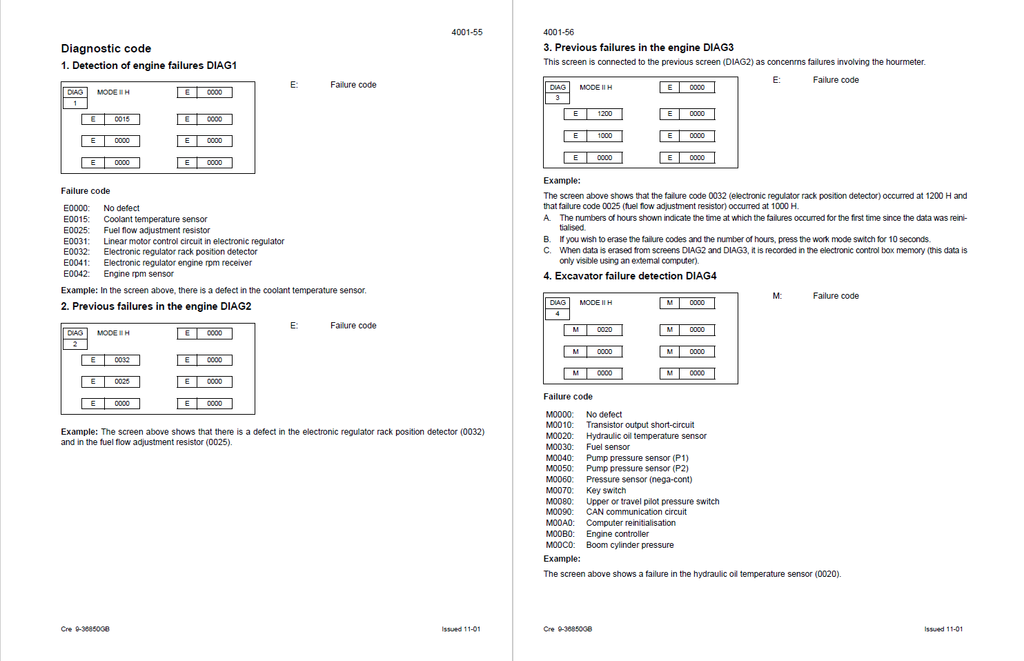
- Deep-Level Electronic Interrogation: Stop guessing and start communicating directly with the machine's ECM networks. This manual decodes the onboard diagnostic matrices, allowing technicians to instantly translate specific fault codes like E0031 (linear motor control circuit) or M0090 (CAN communication circuit). It further mandates using the CAS-30039 service connector kit and CAS Multimeter 1559 to verify exact pinout voltages, such as proving the 24V output at CN6 terminal 28 for the Y4 travel speed solenoid.
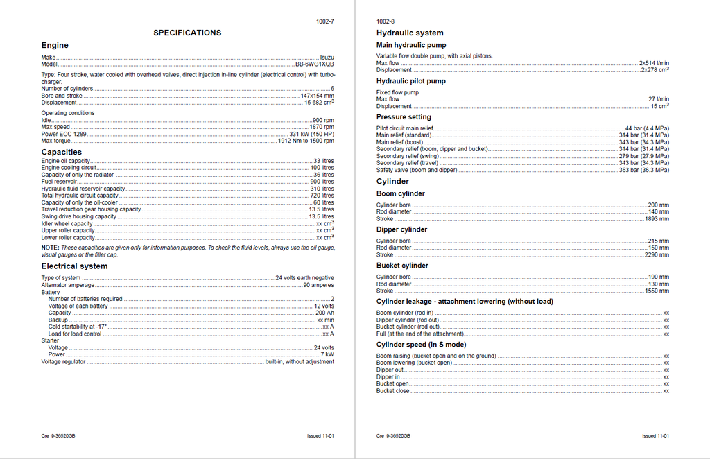
- Absolute Hydraulic Calibration Standards: Master the massive fluid dynamics required to power this 80-ton-class equipment. The guide details how to utilize the CAS 30038 test kit to dial in the primary pump architecture, dictating a strict 314 bar (31.4 MPa) for the standard main relief and exactly 343 bar (34.3 MPa) for power boost circuits. It also provides uncompromising parameters for tuning the pilot network to exactly 44 bar (4.4 MPa).
- Heavy Structural Fastening Architectures: Prevent catastrophic chassis separation under extreme mining loads. The literature outlines the mandatory teardown and reconstruction procedures for the entire lower frame and drive train, dictating massive fastening forces such as the 2746 Nm (280 kgf.m) required for the M36 bolts securing the center frame to the power side frames, and 1307 to 1526 Nm for the M27 reduction gear hardware.
Features & Highlights
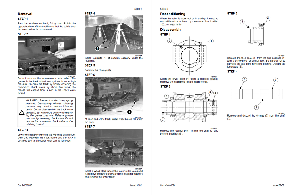
- Micrometer-Level Undercarriage Metrology: Eradicate premature track failures by utilizing factory wear metrics instead of visual estimates. The documentation provides exhaustive inspection thresholds, requiring mechanics to verify a 260.35 mm standard track pitch and mandating a hard replacement limit when the 980 mm sprocket diameter wears down to exactly 965 mm.
- Dynamic Fluid Logic & Spool Architecture: Navigating the massive control valve banks is made straightforward. The manual extensively maps out the internal spool logic and fluid paths, detailing exactly how the boom priority (Y10) and negative flow control (Y11) networks interact to prioritize the pump output when multiple heavy attachments are commanded simultaneously.
- Surgical Decontamination Protocols: Recovering from a destroyed pump requires uncompromising cleanliness to protect the replacement parts. This volume outlines the mandatory hydraulic system depressurization and decontamination sequences, utilizing the specific CAS 10193 vacuum pump kit and CAS 10162A portable filter to extract microscopic debris from the reservoir and lines.
Problem Solver
- Cures Phantom Electrical Draws & Sensor Failures: Stop replacing expensive control boxes blindly. By utilizing the exact resistance benchmarks provided, mechanics can definitively prove a sensor's health—such as verifying a strict 6.08 kΩ resistance at 20°C for the coolant thermistor and 2.45 kΩ for the hydraulic oil sensor—instantly isolating a damaged wiring harness from a physical component failure.
- Resolves Catastrophic Travel Drift: The step-by-step troubleshooting trees permanently eradicate tracking issues. It instructs technicians to connect pressure gauges and verify if the differential between P1 and P2 exceeds 30 bar (3 MPa) during travel, directly pointing to a sticking control pedal spool or a failing negative pressure (N) regulator.
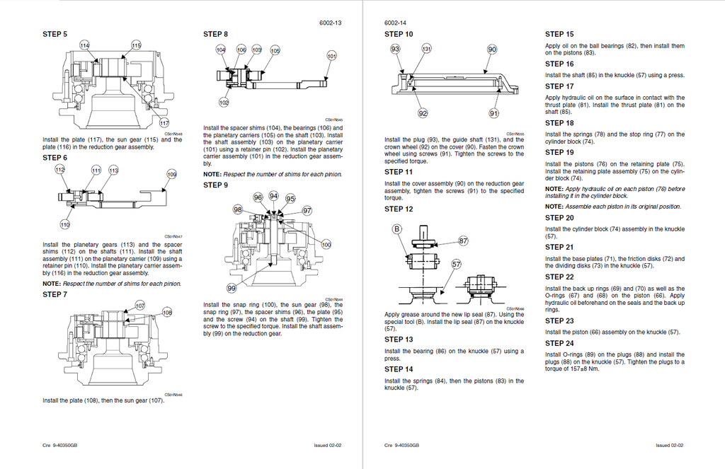
- Prevents Fatal Reassembly Mistakes: Avoid destroying freshly rebuilt planetary reduction gears and fluid motors. The teardown instructions provide absolute wear limits, demanding the immediate replacement of the swing motor cylinder block and pistons the moment the operating clearance exceeds the critical 0.062 mm maximum tolerance.
Important Pre-Purchase Advisories
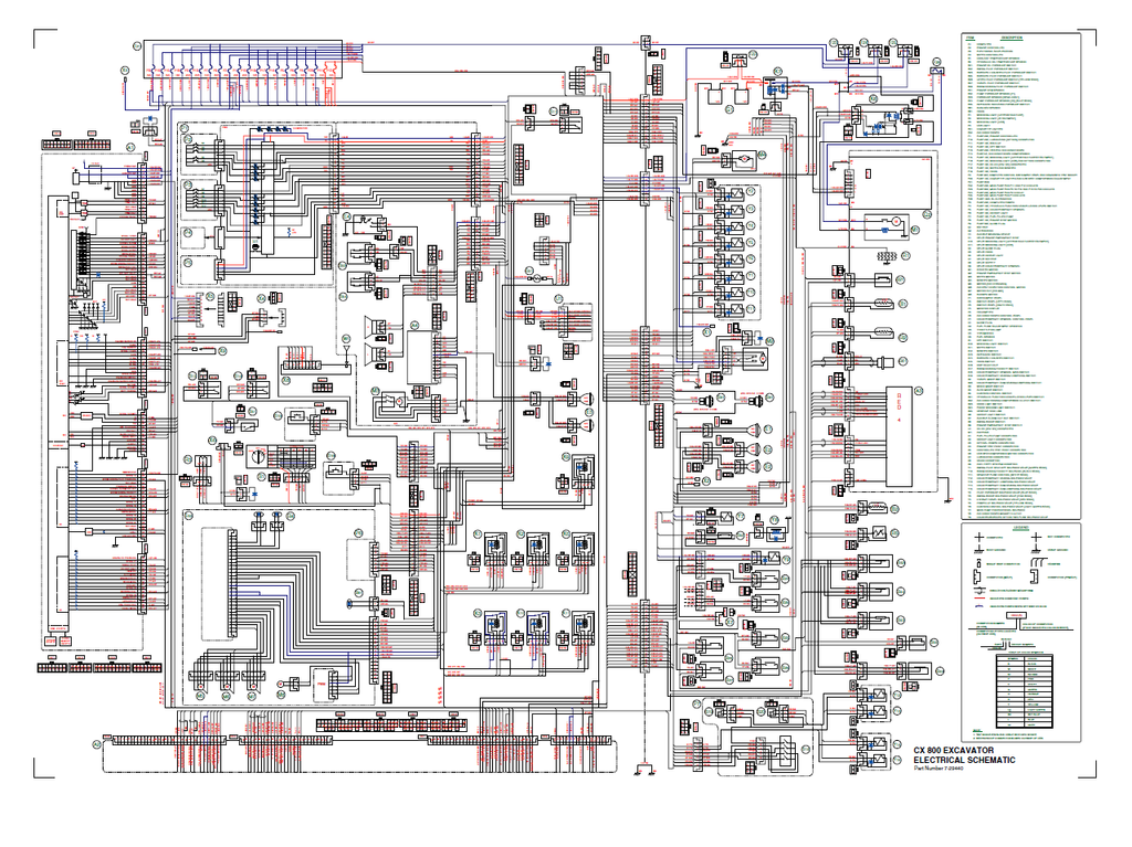
- Complete "Large Format" Schematics Included: Unlike many incomplete service guides, this publication includes the highly detailed, end-to-end electrical wiring schematics (OEM Part Number 7-29440) and complex hydraulic circuit diagrams, fully mapping out all CAN-bus networks, ECM pinouts, and pilot fluid routing.
- Dedicated Engine Block Focus: While this manual exhaustively covers the engine's external removal, installation, electronic acceleration circuits, and onboard ECM fault code decoding (DIAG 1, 2, and 3 screens), the deep internal mechanical teardown of the diesel engine block itself is referred to a separate, dedicated engine service manual by the manufacturer.
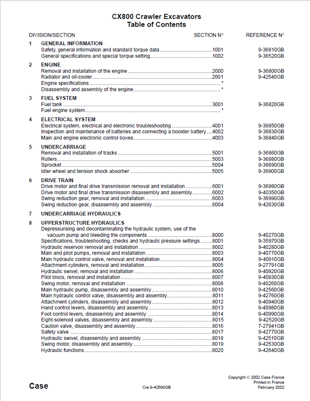
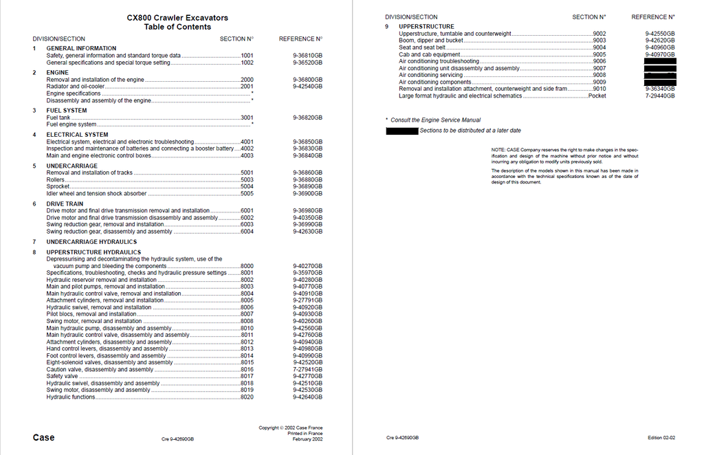
Table of Contents
- General Information
- Safety, general information and standard torque data
- General information
- Safety
- Standard torque data for cap screws and nuts
- General specifications and special torque setting
- Type, serial number and year of manufacture of the machine
- Machine
- Engine
- Serial numbers of the components
- Ingredients
- Hydraulic fluid
- Transmission assembly oil
- Greases
- Engine oil
- Viscosity of oils/Operating range of oils
- Fuel
- Antifreeze/anticorrosive
- Environment
- Plastic and resin parts
- Specifications
- Engine
- Capacities
- Electrical system
- Hydraulic system
- Cylinder
- Control valve
- Swing
- Travel
- Undercarriage
- Attachment
- Weight of components
- Dimensions and wear limit of the track-layer assembly
- Sprocket
- Idler wheel
- Upper roller
- Lower roller
- Track
- Dimensions and wear limits of attachment mobile joints
- Boom foot/Frame
- Boom cylinder foot/Frame
- Boom cylinder head/Boom
- Dipper cylinder foot/Boom
- Boom/Dipper
- Dipper cylinder head/Dipper
- Bucket cylinder foot/Dipper
- Connecting rod/Dipper
- Compensator/Bucket
- Connecting rod/Compensator/Bucket cylinder head
- Dipper/Bucket
- Type, serial number and year of manufacture of the machine
- Safety, general information and standard torque data
- Engine
- Removal and installation of the engine
- Specification
- Torque setting
- Engine
- Removal and installation
- Radiator and oil-cooler
- Specifications
- Changing the radiator or the oil-cooler
- Description
- Removal and installation of the engine
- Fuel System
- Fuel tank
- Specifications
- Fuel tank
- Removal
- Description
- Fuel tank
- Electrical System
- Electrical system, electrical and electronic troubleshooting
- Specifications
- Special tools
- General location of the components (outside the cab)
- General location of the components (inside the cab)
- Fuse box
- Instrument panel
- Operating principles
- Engine checks
- Work mode selection
- H/S/L mode checking
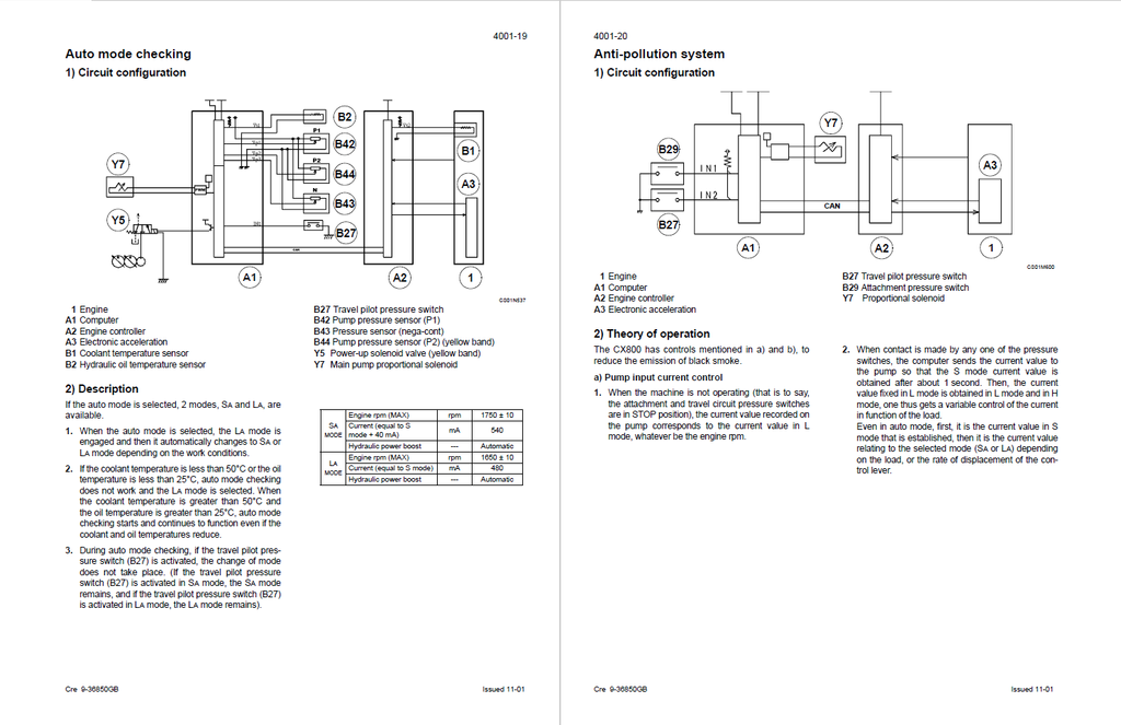
- Auto mode checking
- Acceleration checking
- Engine idle checking (automatic/manual)
- Breaker mode checking
- Automatic engine preheat
- Auto engine warm-up
- Idle checking using the battery voltage and the coolant temperature
- Engine emergency stop
- Back-up mode
- Function locking
- Power boost
- Swing brake
- Travel mode
- Fuel level
- Engine fuel injection pump electronic regulator
- Counterweight removal circuit
- Access and contents of monitor displays (Diagnostic mode)
- Access to monitor displays
- Machine condition
- Diagnostic code
- Machine history
- Re-initialisation
- Warning messages
- Message display
- Excavator model selection procedure
- Changing the language code
- Changing the access code for the anti-theft system
- Troubleshooting
- Prior inspections
- Reading the organisation charts
- Procedures
- Fuel
- Add coolant solution
- Low engine oil pressure
- Overheating
- Defective battery charge circuit
- Electrical system troubleshooting
- Travel
- Electrical inspection of components
- Inspection equipment
- Proportional solenoid
- Engine emergency stop motor
- 8 solenoid valve bank
- Engine rpm sensor
- Coolant solution and hydraulic oil temperature sensor
- Pressure sensor
- Inspection and maintenance of batteries and connecting a booster battery
- Safety instructions
- Specifications
- Computer and engine controller
- Removal
- Computer
- Engine controller
- Installation
- Electrical system, electrical and electronic troubleshooting
- Undercarriage
- Removal and installation of tracks
- Specifications
- Special torque settings
- Special tools
- Tracks set
- Description
- Removal
- Rollers
- Specifications
- Special torque settings
- Special tools
- Lower roller
- Description
- Removal
- Reconditioning
- Disassembly
- Inspection
- Assembly
- Installation
- Upper roller
- Description
- Removal
- Reconditioning
- Model 1 removal
- Inspection
- Assembly
- Model 2 removal
- Inspection
- Assembly
- Installation
- Sprocket
- Idler wheel and tension shock absorber
- Disassembly
- Inspection
- Assembly
- Leakage test
- Disassembling and assembling the tension shock absorber
- Description
- Disassembly
- Assembly
- Track tension cylinder
- Description
- Removal
- Disassembly
- Inspection
- Assembly
- Removal and installation of tracks
- Drive Train
- Drive motor and final drive transmission removal and installation
- Travel motor/reduction gear assembly
- Removal and installation
- Travel motor/reduction gear assembly
- Drive motor and final drive transmission disassembly and assembly
- Specifications
- Special torque settings
- Special tools
- Travel drive motor and reduction gear
- Disassembly
- Inspection
- Motor
- Reduction gear
- Assembly
- Swing reduction gear, removal and installation
- Swing reduction gear, disassembly and assembly
- Drive motor and final drive transmission removal and installation
- Undercarriage Hydraulics
- Upperstructure Hydraulics
- Depressurising and decontaminating the hydraulic system, use of the vacuum pump and bleeding the components
- Special tools
- Releasing pressure in the hydraulic system
- Bleeding air from the main hydraulic system components
- Hydraulic pump
- Attachment cylinders
- Hydraulic swing motor
- Vacuum pump
- Specifications, troubleshooting, checks and hydraulic pressure settings
- Specifications
- Special tools
- Tester
- Identification of hydraulic components
- Pump
- Control valve
- Solenoid valve block
- Preparation before inspection
- Releasing pressure in the hydraulic system
- Checking and setting procedure
- Location of secondary relief valves
- Main pilot system relief
- Checking the pilot accumulator
- Main relief (standard)
- Adjusting the 2-stage relief level
- Adjusting the standard pressure
- Attachment secondary relief
- Swing port secondary relief
- Travel port secondary relief
- Checking the swing brake release pressure
- Checking the pressure delivered by the proportional valve
- Checking for leaks on the travel motor
- Checking the swing motor for leaks
- Troubleshooting
- Travel drift
- Not possible to select 2nd travel speed
- No swing or slow swing
- With the excavator on a slope, the swing brake does not hold
- No movement on any function
- Lack of power or speed on one of the attachment movements
- Not possible to select cushion control
- The boom or the dipper does not lower
- Hydraulic reservoir removal and installation
- Specifications
- Hydraulic reservoir
- Removal
- Installation
- Description
- Main and pilot pumps, removal and installation
- Specifications
- Special torque settings
- Main hydraulic pump
- Removal and installation
- Pilot pump
- Removal and installation
- Hydraulic pump coupling
- Removal
- Inspection
- Installation
- Main hydraulic control valve, removal and installation
- Special torque settings
- Description
- Main control valve
- Removal and installation
- Attachment cylinders, removal and installation
- Description
- Removal
- Installation
- Bucket cylinder
- Description
- Removal
- Installation
- Hydraulic swivel, removal and installation
- Pilot blocs, removal and installation
- Swing motor, removal and installation
- Main hydraulic pump, disassembly and assembly
- Specifications
- Special torque settings
- Hydraulic pump
- Locating the ports
- Regulator control
- Removing the regulator
- Removing the pump
- Inspection
- Installing the regulator
- Installing the hydraulic pump
- Main hydraulic control valve, disassembly and assembly
- Torque settings
- Special tools
- Description
- Section for dipper 2, boom 1, bucket, RH travel and straight-line travel
- Removing the section
- Removing the boom load holding valve
- Removing from the non-return check valves
- Removing the boom priority block
- Removing the by-pass valve
- Removing the RH travel plug
- Remove the non-return check valves
- Removing the straight-line travel pilot
- Removing the main relief
- Removing the boom raising, boom lowering, bucket opening and bucket closing port secondary reliefs
- Removing the negative control relief
- Removing the dipper spools 2, boom 1, bucket, RH travel and straight-line travel
- Installation
- Installing the dipper spools 2, bucket, boom 1, RH travel and straight-line travel
- Installing the negative control relief
- Installing the boom raising, boom lowering, bucket opening and bucket closing port secondary reliefs
- Installing the main relief
- Installing the straight-line travel pilot
- Installing the RH travel plug
- Installing the non-return check valves
- Installing the by-pass valve
- Installing the boom priority block
- Installing the non-return check valves
- Installing the boom load holding valve
- Removing the section for dipper 1, option, boom 2, swing, LH travel
- Removing the dipper and boom load holding valve
- Removing the non-return check valves
- Removing the plug
- Removing the dipper out and dipper in port secondary reliefs
- Removing the by-pass valve
- Removing the swing priority and boom priority block
- Removing the straight-line travel pilot
- Removing the control shuttle block
- Removing the negative control relief
- Removing the option plates
- Removing the PP port restrictor
- Removing the PY port restrictor
- Removing the spools for dipper 1, option, boom 2, swing, LH travel
- Installation
- Installing the spools for dipper 1, option, boom 2, swing, LH travel
- Installing the option plates
- Installing the PP port restrictor
- Installing the PY port restrictor
- Installing the negative pressure control relief
- Installing the control shuttle block
- Installing the straight-line travel pilot
- Installing the swing priority and boom priority block
- Installing the by-pass valve
- Installing the dipper out and dipper in port secondary reliefs
- Installing the plug
- Installing the non-return check valves
- Installing the dipper and boom load holding valve
- Dipper load holding valve and boom load holding valve
- Disassembly
- Inspection
- Assembly
- Removing the option non-return check valves, boom 1 and boom 2
- Inspection
- Assembly
- Removing the straight-line travel non-return check valve, option
- Inspection
- Assembly
- Removing the non-return check valve
- Inspection
- Assembly
- Spool assembly
- Disassembly
- Inspection
- Assembly
- Boom raising, boom lowering, dipper out, dipper in, bucket opening and bucket closing port secondary relief
- Disassembly
- Inspection
- Assembly
- Boom priority block and swing priority block
- Disassembly
- Inspection
- Assembly
- Negative control reliefs
- Disassembly
- Inspection
- Assembly
- Straight-line travel pilot
- Disassembly
- Inspection
- Assembly
- Control shuttle block
- Disassembly
- Inspection
- Assembly
- Restrictor
- Disassembly
- Inspection
- Assembly
- Main relief
- Disassembly
- Inspection
- Assembly
- Attachment cylinders, disassembly and assembly
- Boom cylinder description
- Dipper cylinder description
- Bucket cylinder description
- Special tools
- Cylinders
- Disassembly
- Inspection
- Assembly
- Hand control levers, disassembly and assembly
- Specifications
- Control lever
- Description
- Disassembly
- Inspection
- Assembly
- Foot control levers, disassembly and assembly
- Control pedals
- Description
- Disassembly
- Inspection
- Assembly
- Control pedals
- Eight-solenoid valves, disassembly and assembly
- Caution valve, disassembly and assembly
- Safety valve
- Hydraulic swivel, disassembly and assembly
- Swing motor, disassembly and assembly
- Hydraulic motor
- Disassembly
- Inspection
- Cross sectional view
- Assembly
- Troubleshooting
- Hydraulic motor
- Hydraulic functions
- List of functions
- Controls in neutral position
- Travel high speed circuit
- Low speed travel circuit
- Straight-line travel circuit
- Swing circuit
- Swing priority circuit
- Boom raising circuit
- Boom priority circuit with the swing
- Boom priority circuit with the bucket
- Boom lowering, load holding circuit
- Boom lowering additional flow circuit
- Dipper outlet circuit
- Dipper in circuit
- Dipper in additional supply circuit
- Bucket opening circuit
- Bucket closing circuit
- Multifunction circuit, shears function
- Breaker circuit
- Removing the counterweight
- Pump with engine stopped
- Pump with engine running, controls at neutral, maximum speed
- Pump with engine running, one control operated, one flow
- Pump with engine running, two controls operated, two flows
- Pump working at the regulated mechanical torque value (engine running)
- Depressurising and decontaminating the hydraulic system, use of the vacuum pump and bleeding the components
- Upperstructure
- Upperstructure, turntable and counterweight
- Special torque settings
- Specifications
- Upperstructure
- Inspection
- Removal
- Installation
- Turntable
- Counterweight
- Boom, dipper and bucket
- Bucket
- Description
- Removal
- Installation
- Dipper
- Description
- Removal
- Installation
- Boom
- Description
- Removal
- Installation
- Bucket
- Seat and seat belt
- Specifications
- Operator’s seat
- Description
- Removal
- Repose
- Cab and cab equipment
- Specification
- Special torque settings
- Cab
- Removal
- Repose
- Heating block/Air-conditioning block
- Description
- Removal
- Installation
- Air conditioning unit disassembly and assembly
- Removal and installation attachment, counterweight and side frame
- Torque specifications
- Matters to requiring attention
- Preparation
- Preparing to assembly/disassembly work area
- Purpose
- Matters requiring attention
- Overall layout
- Preparation process
- Positioning for major components layout
- Description
- Unloading phase 1
- Purpose
- Warning
- Procedure for unloading
- Unloading phase 3
- Unloading the upperstructure
- Purpose
- Warning
- Procedure for unloading
- Task summary N°1 for connection of lower side frames to upperstructure
- Assembly task N°1 (one side)
- Purpose
- Warning
- Procedure for task summary N°1 for connection of lower side frames to upperstructure
- Connection of the side frame to the center frame
- Task summary N°2 for connection of lower side frames to upperstructure
- Assembly task N°2 (remaining side frames)
- Purpose
- Warning
- Fitting work on the counter side
- Procedure for task summary N°2 for connection of lower side frames to upperstructure
- Connection of the counter side side frame to the center frame (after swing motion is made)
- Mounting travel motor lines
- Mounting work procedure
- Purpose
- Warning
- Operational testing after assembly work
- Disassembly work
- Bucket removal
- Dipper removal
- Boom cylinder removal
- Boom removal
- Counterweight removal
- Removal of travel motor piping and small accessories
- Separation of upperstructure and undercarriage and loading
- Large format hydraulic and electrical schematics
- Upperstructure, turntable and counterweight