

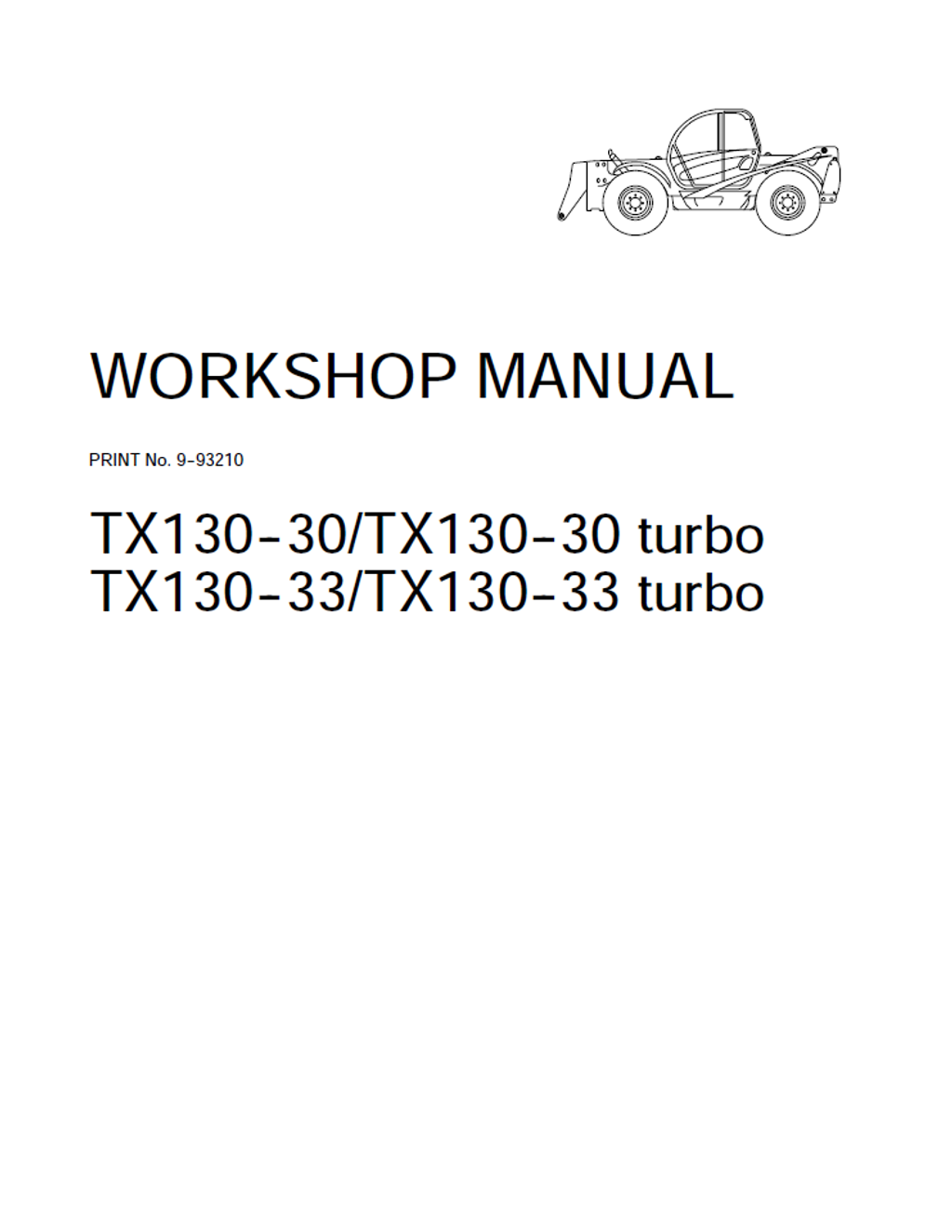
CASE Construction TX130-30, TX130-30 Turbo, TX130-33, TX130-33 Turbo Telehandler Workshop Manual 9-93210 English
Official Manual Overview
Elevate your workshop capabilities with this uncompromising OEM Workshop Manual engineered specifically for the CASE TX130-30 and TX130-33 Telehandlers (including all Turbo variants). Going far beyond routine maintenance, this master document delivers dealership-level teardown and rebuild instructions for the complete powertrain, heavily featuring the 4x3 Powershift transmission and the unabridged overhaul procedures for the CNH F4GE series diesel engines (F4GE0404B and F4GE0454C). Mechanics will find highly specialized benchmark data, from micrometer-level engine metrology (such as the strict 82.99 mm main journal limits) to intricate dynamic pressure testing for the 175-bar OSPQ steering circuit and 350-bar telescopic boom relief valves. Fully equipped with comprehensive electrical harness pin-outs, load momentum device calibration protocols, and step-by-step hydraulic cylinder resealing guides, this technical blueprint is the definitive tool to eradicate diagnostic guesswork and restore your telescopic handler to absolute factory precision.
- Brands: CASE Construction
- Equipment Type: Telehandler
- Manuals Type: Workshop Manual
- Machine Model: TX130-30, TX130-30 Turbo, TX130-33, TX130-33 Turbo
- Serial Number: N/R
- Region: N/R
- Book Code: 9-93210
- Issued: Printed by Satiz - Turin (Italy) - December, 2004
- Language: English
- Pages: 495
- File Format: PDF (Searchable)
Core Selling Points
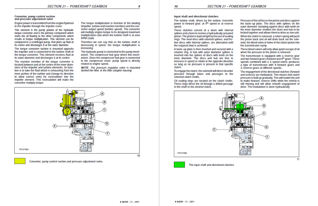
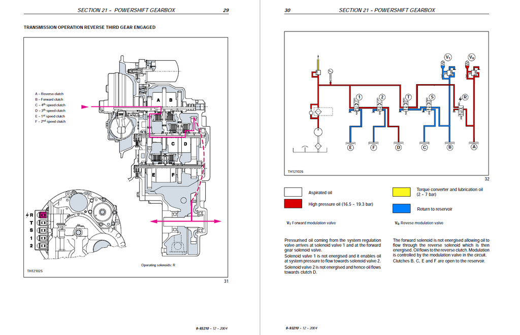
- Dynamic Powershift Transmission Diagnostics: Do not attempt to rebuild the gearbox blindly. This documentation delivers high-level hydraulic pressure testing protocols for the 4x3 Powershift transmission. It specifies connecting gauges to exact testing ports to verify that clutch circuit pressures are locked strictly at 16.5 to 19.5 bar (240–280 psi), and mandates that the torque converter cooler circuit maintains a precise 2 to 7 bar at 2000 rpm.
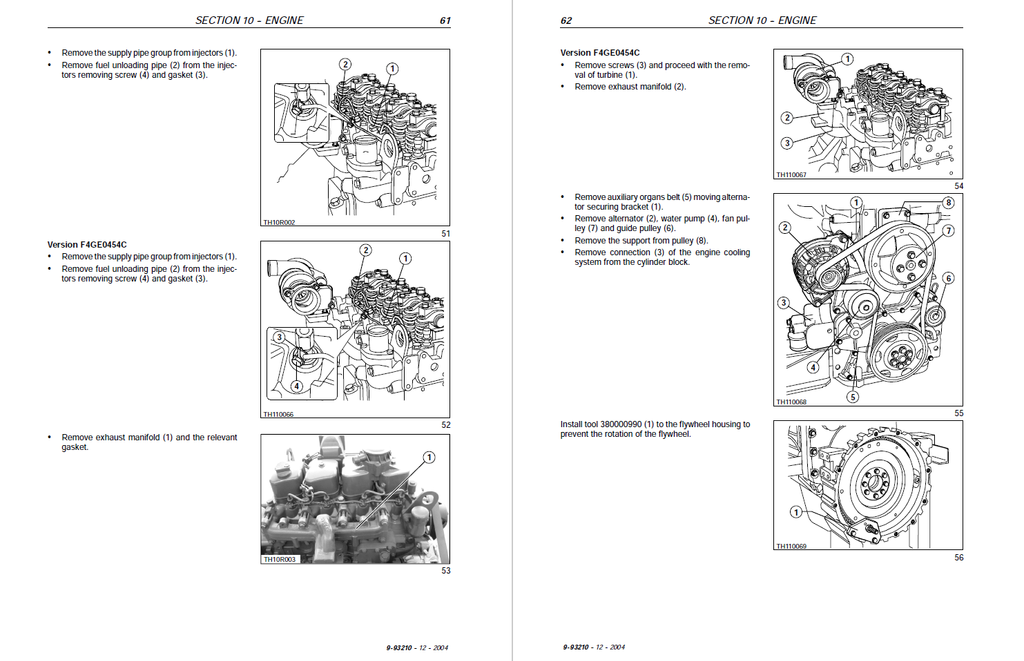
- Micrometer-Level Block Reconstruction: Bypass generic engine guides. This manual provides the unabridged teardown procedures for the CNH F4GE0404B and F4GE0454C diesel engines. It strictly mandates cylinder block grinding if the head mounting face flatness error exceeds 0.075 mm, dictates exact camshaft lifting limits (7.239 mm for exhaust lobes), and enforces multi-phase fastening sequences—such as torquing M16 cylinder head screws to 200 ±20 Nm.
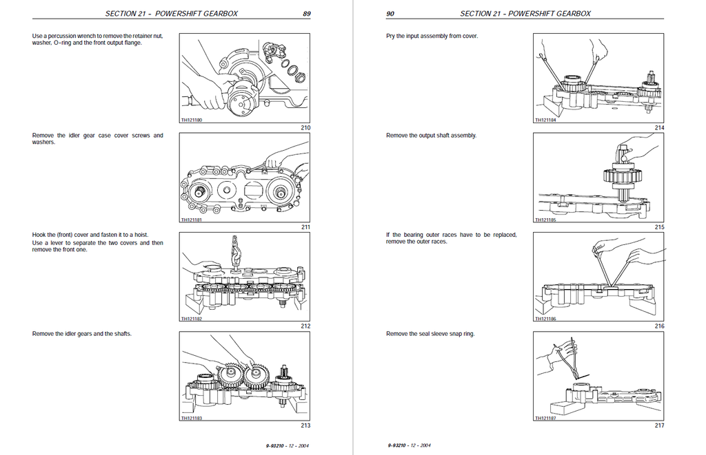
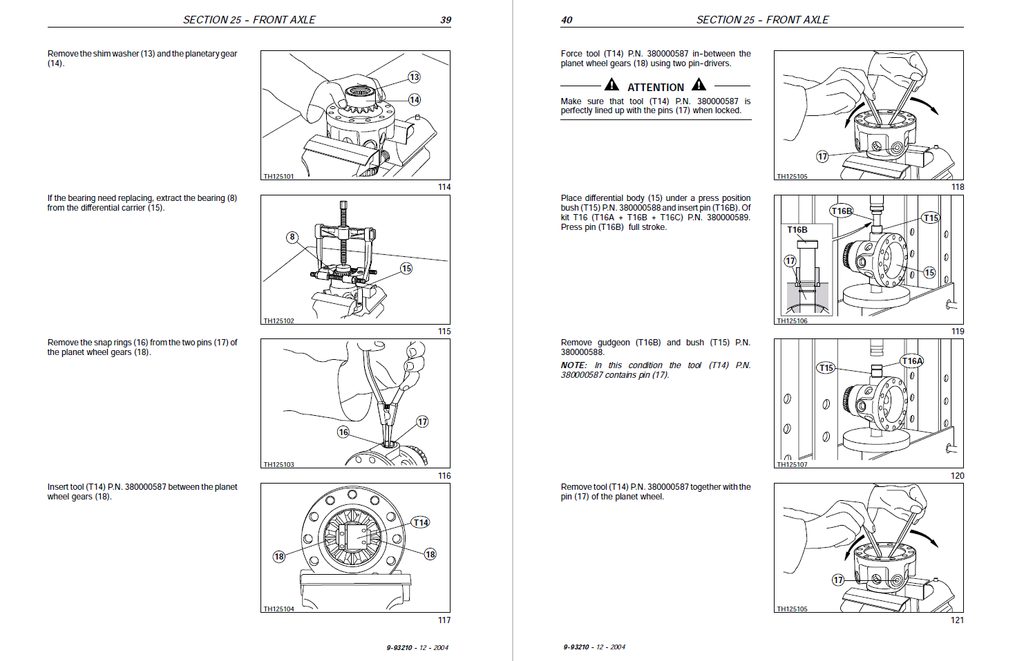
- Heavy-Duty Axle & Driveline Overhaul: Execute complete planetary hub and differential rebuilds with absolute factory certainty. The text enforces exact preload metrics, requiring technicians to adjust the pinion rolling torque to exactly 120–170 Ncm and subsequently torque the main pinion nut to a massive 500 Nm utilizing the proprietary 380000591 special wrench.
Features & Highlights
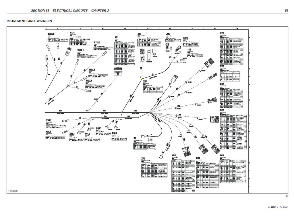
- Pin-Level Electrical Schematics: Take total control over the machine's complex wiring networks. The electrical section breaks down detailed harness routing, identifying multi-way connector interfaces like the X137 (17-ways work selection controller) and the X25 (21-ways dashboard-engine line) to physically trace continuity and troubleshoot individual modules (such as the K19 engine cut-off relay).
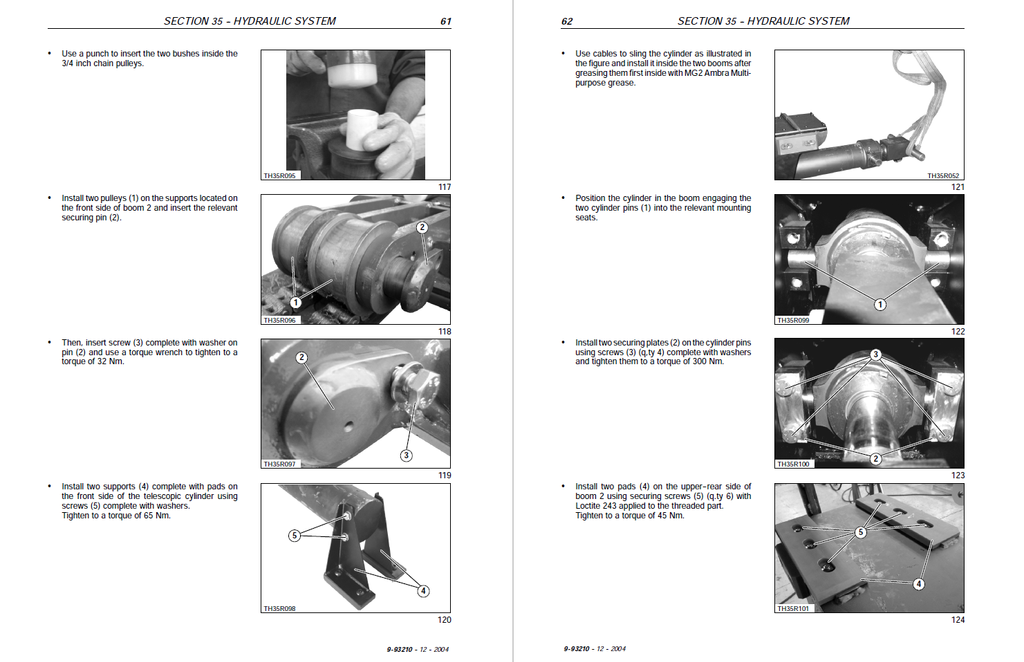
- Fluid Power Actuator Resealing: Reconstruct your telescopic boom cylinders without risking structural failure. The guide provides deep teardown procedures for the inner telescopic and lifting actuators, detailing the exact application of Loctite 638/648 and enforcing extreme tightening specifications, such as 5500 to 6000 Nm for the lifting cylinder rod ring.
- Proprietary Tooling & Metrology Registries: The documentation completely eliminates guesswork by mapping out all specialized service tools required for major component overhauls. It details the exact usage of the 380000827 bore gauge for cylinder sleeve measurements and the 380000976 tool to check intake/exhaust valve spring flexing limits.
Problem Solver
- Resolves Hydrostatic Transmission Drop-outs: Stop blindly replacing expensive clutch packs. The manual features dedicated troubleshooting matrices for the powershift system, guiding technicians to use specific test ports to trace internal pressure drops. If a directional clutch slips, the logic flow dictates checking the forward (VT) or reverse (VR) modulation valves rather than assuming catastrophic mechanical failure.
- Eradicates Elusive Diesel Engine Faults: Transform erratic performance into calculated repair steps. The engine flowcharts systematically isolate issues such as "The engine smokes dark grey" or "Knocking found in the crankshaft", leading mechanics to scientifically verify static pump timing or measure connecting rod out-of-round tolerances before ordering replacement parts.
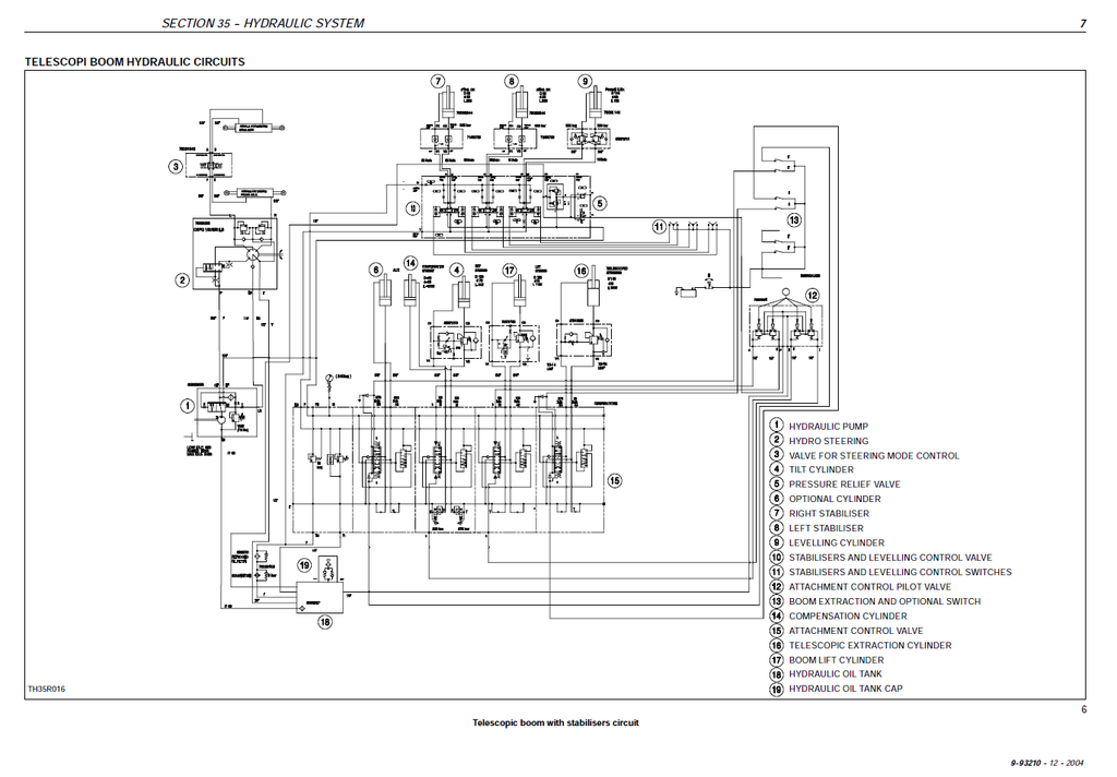
- Isolates Complex Hydraulic Failures: Master the load-sensing priority steering and boom circuits. The manual allows technicians to test the delivery side flow divider, verifying that the steering priority circuit receives exactly 175 bar, while ensuring the inner telescopic cylinder pressure relief valves are precisely calibrated to 350 bar on the stem side (V1) and 260 bar on the plunger side (V2).
Important Pre-Purchase Advisories
- Geographical Variations Notice: The manual notes that the layout of cab controls and instrument panels may vary slightly depending upon options fitted to meet specific legislation in different countries.
- Integrated Schematic Layout: Complete wiring diagrams (Diagrams 1 through 10, covering Transmission, Boom Control, Stabilizers, Wheel Alignment, etc.) are integrated directly into Chapter 2 of the Electrical System section for in-depth harness tracing.
Table of Contents
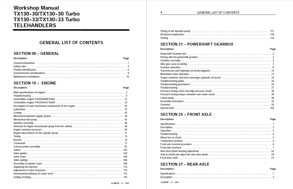
- GENERAL
- General instructions
- Safety rules
- Product identification
- Environmental considerations
- Maintenance techniques
- ENGINE
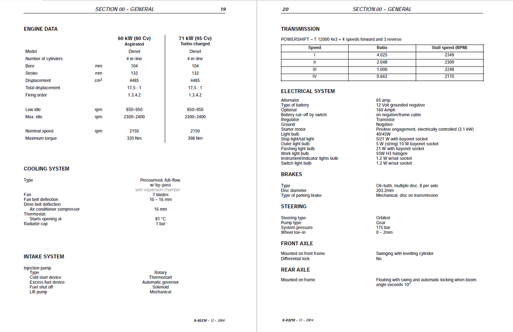
- Main specifications of engines
- Troubleshooting
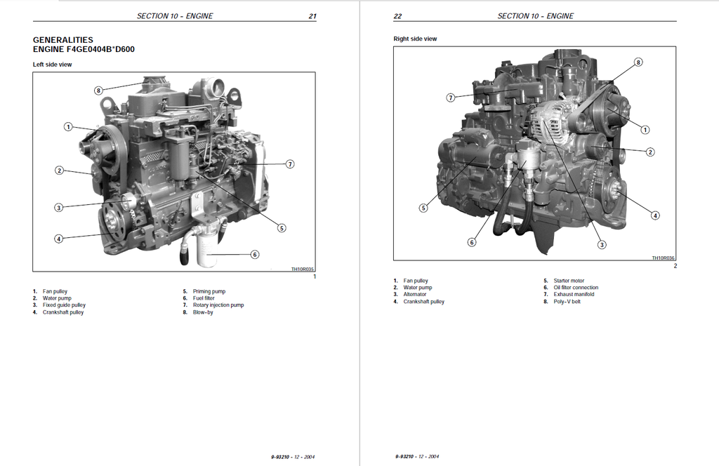
- Generalities engine F4GE0404B*D600
- Generalities engine F4GE0454C*D600
- Description of main mechanical components of the engine
- Lubrication
- Cooling
- Mechanical injection supply system
- Mechanical fuel pump
- Injection assembly
- Removal of engine transmission group from the vehicle
- Engine overhaul on bench
- Repair interventions on the cylinder group
- Timing
- Bushes
- Crankshaft
- Conrod-piston assembly
- Valves
- Valve guides
- Valve seats
- Valve springs
- Assembly of cylinder head
- Replacing the injectors
- Adjustment of valve clearance
- Removal/reinstallation of rocker arms
- Setting of timing
- Timing of the injection pump
- Electrical components
- Tooling
- POWERSHIFT GEARBOX
- Powershift Gearbox 4x4
- Driving with the powershift gearbox
- Gearbox assembly
- Idler gear case assembly
- Gearbox operation
- Transmission and Hydraulic oil circuit diagrams
- Modulation valve operation
- Torque converter and heat exchanger hydraulic oil circuit
- Troubleshooting guide
- Troubleshooting procedures
- Troubleshooting
- Pressure testing clutch and high pressure circuit
- Pressure testing torque converter and cooler circuit
- Check points
- Assembly instructions
- Overhaul
- Special tools
- FRONT AXLE
- Specifications
- Description
- Operation
- Troubleshooting
- Wheel toe-in check
- REAR AXLE
- Description
- Operation diagram
- Component overhaul
- Rear axle removal procedure
- Overhaul
- BRAKES
- Specifications
- Power brakes
- HYDRAULIC SYSTEM
- Technical data
- Description and operation
- Introduction
- Steering system hydraulic circuit
- Steering valve
- Telescopic boom hydraulic circuit
- Component operation
- Hydraulic pump
- Delivery side divider valve
- Pressure reduction valve
- Front loader controls
- Balancing valves
- Power steering (OSPQ)
- Telescopic boom distributor
- Auxiliary control distributor
- Cylinders
- Booms
- ELECTRICAL SYSTEM
- Chapter 1 – Electrical system general
- Electrical equipment specifications
- Electrical system and fuses
- Controls and instruments
- Procedure for the calibration of the load momentum system
- Bulb replacement
- Protecting the electrical systems during charging or welding
- Starting the machine using jump leads
- Temporary wiring repairs
- Electrical system-general fault finding
- Chapter 2 – Circuit diagrams
- List of connectors
- List of components
- How to use the circuit diagrams
- Diagram 1: Starting/Recharge/Warning/Indicators lights
- Diagram 2: Transmission
- Diagram 3: Wheel alignment/Hydraulic solenoids/Brake system
- Diagram 4: Boom control
- Diagram 5: Stabiliser
- Diagram 6: Lights/Front wiper
- Diagram 7: Work lamps/Roof beacon light
- Diagram 8: Load momentum device / Upper wiper
- Diagram 9: Heating / Radio / Power socket / Ceiling light
- Diagram 10: Conditioner
- Chapter 3 -- Wiring list
- Instrument panel wiring
- Cab wiring
- Front wiring
- Rear wiring
- Engine wiring
- Chapter 1 – Electrical system general
- AIR CONDITIONING UNIT
- AIR CONDITIONING UNIT
- Operating instructions
- Cab climate
- Cab climate controls
- Air conditioning system
- Service precautions
- Tool connections
- Discharging
- Refrigerant charging
- Leak inspection
- Special tools
- Troubleshooting