

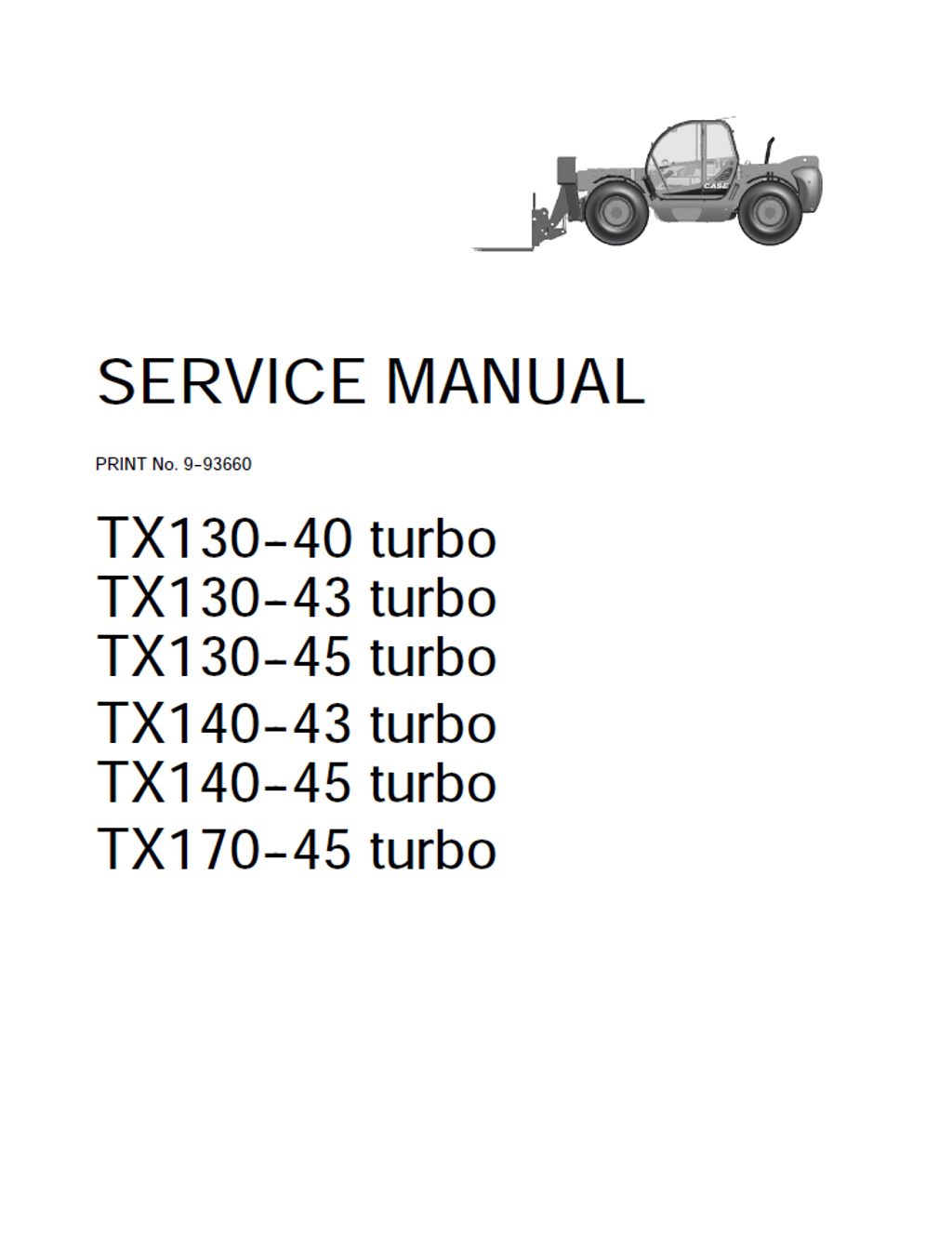
CASE Construction TX130-40 turbo, TX130-43 turbo, TX130-45 turbo, TX140-43 turbo, TX140-45 turbo, TX170-45 turbo Telescopic Handler Service Manual 9-93660 English
Official Manual Overview
Revolutionize your heavy-equipment service capabilities with this unabridged OEM Service Manual explicitly engineered for the CASE TX-Series Turbo Telehandlers (covering the TX130, TX140, and high-reach TX170 turbocharged variants). Going far beyond routine preventative maintenance, this master blueprint delivers dealership-level teardown procedures, uniquely embedding the complete internal engine overhaul protocols for the Tier 2 F4BE0484 3.9L Turbocharged diesel powerplants—dictating micrometer-level metrology such as the strict 82.99 mm crankshaft main journal limit. Powertrain mechanics will find exhaustive hydraulic flow matrices and diagnostic testing standards for the 4x3 Powershift transmission, requiring technicians to verify forward/reverse clutch circuit pressures at exactly 16.5 to 19.3 bar. The guide enforces uncompromising structural calibrations, demanding a massive 5500–6000 Nm torque application for the main lifting cylinder rod, alongside deep-level Rexroth electronic controller diagnostics and joystick potentiometer benchmarking (mandating a precise 2.2V neutral baseline). Fully equipped with high-resolution electrical topologies and planetary axle rebuild charts, this is the definitive weapon to eradicate diagnostic guesswork.
- Brands: CASE Construction
- Equipment Type: Telescopic Handlers
- Manuals Type: Service Manual
- Machine Model: TX130-40 turbo, TX130-43 turbo, TX130-45 turbo, TX140-43 turbo, TX140-45 turbo, TX170-45 turbo
- Serial Number: N/R
- Region: N/R
- Book Code: 9-93660
- Issued: N/R
- Language: English
- Pages: 486
- File Format: PDF (Searchable)
Core Selling Points
- Integrated Tier 2 Engine Reconstruction: Unlike standard telehandler documentation, this volume provides the unabridged cylinder block and head grinding protocols for the F4BE0484 turbocharged diesel engine. It enforces exact micrometer metrology, demanding technicians verify the intake and exhaust valve stem diameters are precisely 7.96 to 7.98 mm, and strictly limits maximum cylinder head metal removal to exactly 0.13 mm to prevent compression ratio failures.
- Extreme Actuator Metrology & Torque: Guarantee structural safety when overhauling heavy-duty lifting and compensation cylinders. The guide breaks down the complex inner and outer telescopic modules, mandating an immense 5500 to 6000 Nm locking torque for the main lifting cylinder rod nut, alongside precise 1300 to 1350 Nm fastening metrics for the 17-meter model's outer extensions.
- Powershift Driveline Restoration: Eliminate planetary gear guesswork. The manual delivers step-by-step disassembly charts for the 4x3 transmission and Carraro axles. It dictates strict reassembly rules, such as torquing the transmission modulation and inching valves to 81–88 Nm, and adjusting the front steering knuckle pivot pins to exactly 140 Nm using the cross-tightening method.
Features & Highlights
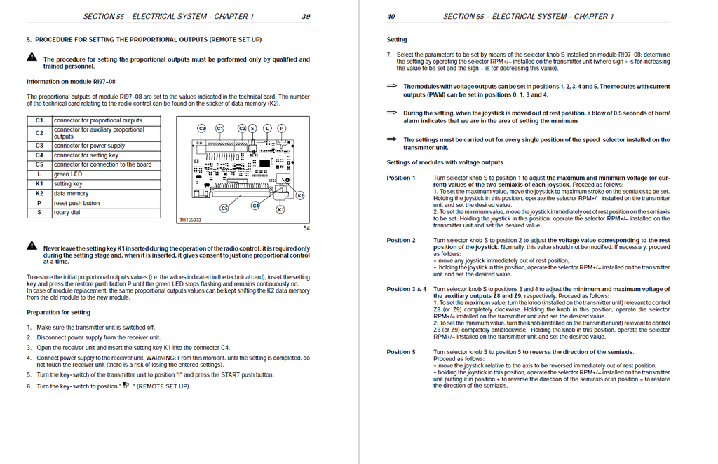
- Advanced Rexroth Electro-Hydraulic Calibration: Master the personnel carrier platform and joystick control modules. Utilizing the proprietary BB3 Diagnostic Instrument (Tool 380001303), technicians are guided through the exact digital menu sequences to calibrate the APC50 controller, locking the joystick potentiometer neutral baseline strictly at 2.2 Volts and setting the full-stroke extension at precisely 4.0 Volts.
- Dynamic Hydrostatic Pressure Benchmarking: Scientifically evaluate the fluid power health of the transmission. The manual maps out dedicated test ports to verify that the powershift forward and reverse clutch system pressure is holding tightly between 16 to 19 bar (with a 13 bar minimum at idle), while ensuring the torque converter cooler circuit maintains a healthy 2 to 7 bar at 2000 RPM.
- High-Resolution Harness Topologies: Trace voltage drops with absolute clarity. The documentation contains complete electrical blueprints covering wheel alignment, arm controls, and stabilizers. It breaks down multi-way connections—like the 28-way APC50 controller interface (X24) and the 21-way control unit connector (XC8)—allowing mechanics to physically pinpoint wire continuity and sensor signals.
Problem Solver
- Resolves Elusive Transmission Slippage: Stop blindly replacing expensive clutch packs. The diagnostic charts systematically isolate driveline power loss. By tapping into the designated clutch pressure ports, mechanics can definitively prove whether a sluggish shift is caused by a failing charging pump, a clogged torque converter filter, or internal seal leakage before dropping the idler gear case.
- Defeats Dangerous Braking Failures: Transform severe brake fading into calculated repairs. The guide targets specific faults like "Insufficient braking" by instructing technicians to manually verify the wet disc brake stack thickness through the oil level port. It mandates a strict 4.5 mm minimum clearance, preventing catastrophic axle overheating and fluid evaporation during heavy-load transport.
- Eradicates Engine Knocks and Stalling: Isolate F4BE0484 fuel delivery issues scientifically. The troubleshooting matrices guide mechanics to evaluate the Bosch VE4/12 F rotary injection pump, checking delivery calibration on the bench and adjusting the valve clearance (0.039 to 0.079 mm stem-to-guide play) rather than assuming catastrophic crankshaft bearing failure.
Important Pre-Purchase Advisories
- Complete Powertrain Coverage Included: Unlike many equipment manuals that omit deep engine data, this volume explicitly includes the complete bench overhaul, timing setting, and mechanical injection calibration for the F4BE0484 diesel engine. No secondary engine manual is required to execute a full block rebuild.
Table of Contents
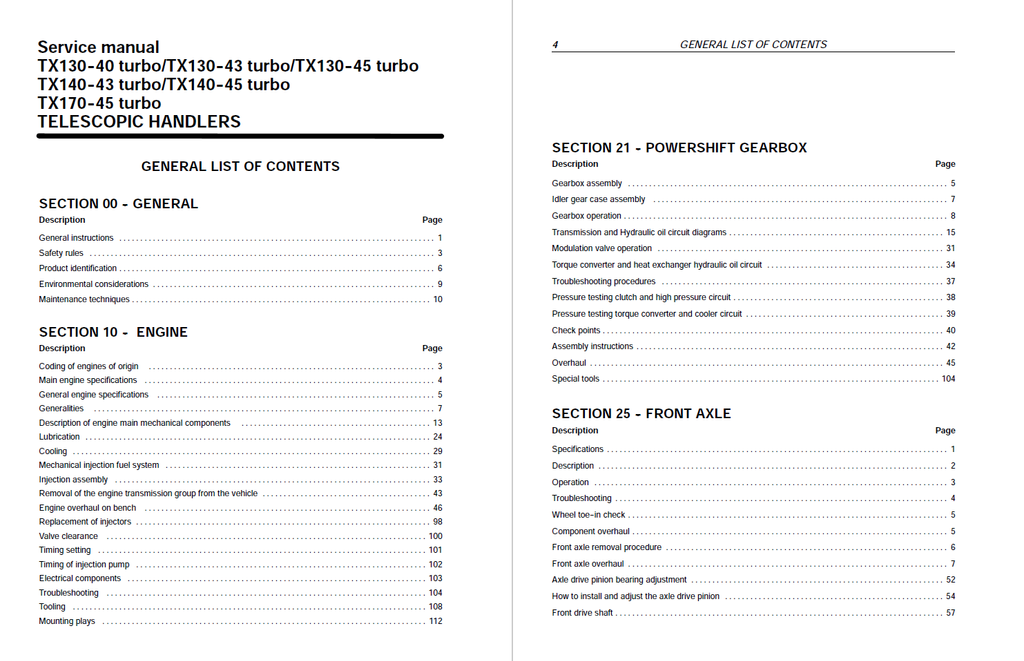
- GENERAL
- General instructions
- Safety rules
- Product identification
- Environmental considerations
- Maintenance techniques
- ENGINE
- Coding of engines of origin
- Main engine specifications
- General engine specifications
- Generalities
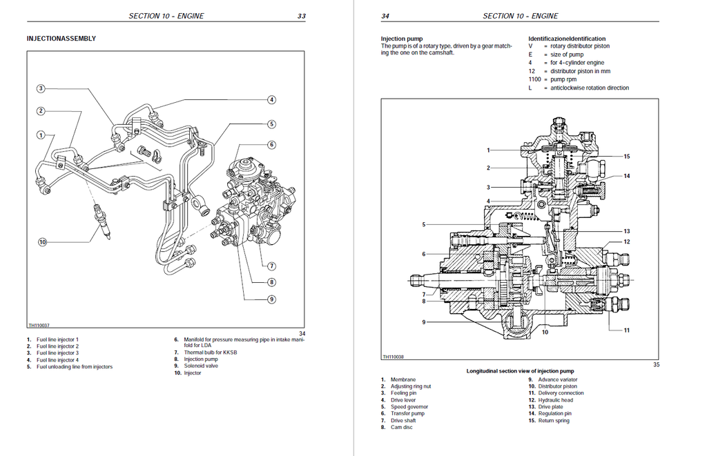
- Injection assembly
- Removal of the engine transmission group from the vehicle
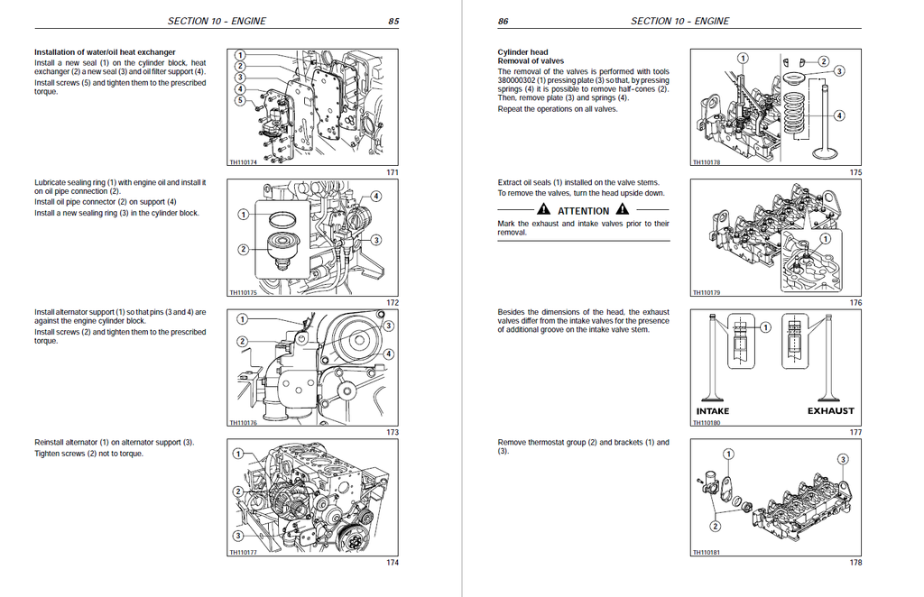
- Engine overhaul on bench
- Replacement of injectors
- Valve clearance
- Timing setting
- Timing of injection pump
- Electrical components
- Troubleshooting
- Tooling
- Mounting plays
- POWERSHIFT GEARBOX
- Gearbox assembly
- Idler gear case assembly
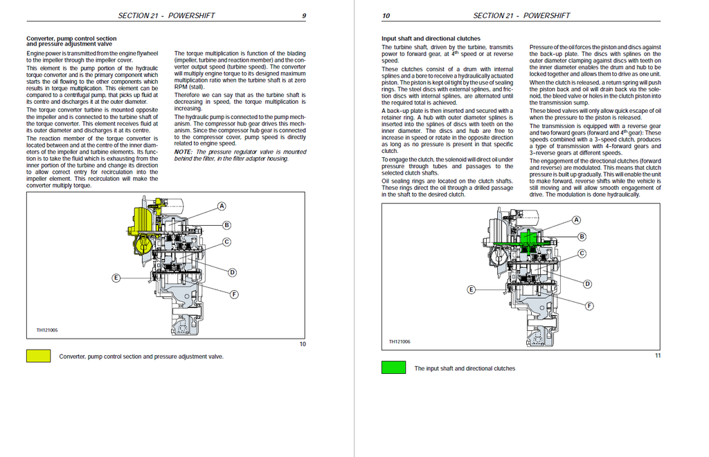
- Gearbox operation
- Transmission and Hydraulic oil circuit diagrams
- Modulation valve operation
- Torque converter and heat exchanger hydraulic oil circuit
- Troubleshooting guide
- Troubleshooting procedures
- Troubleshooting
- Pressure testing clutch and high pressure circuit
- Pressure testing torque converter and cooler circuit
- Check points
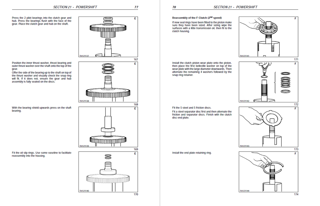
- Assembly instructions
- Overhaul
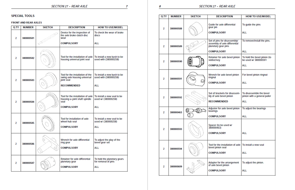
- Special tools
- FRONT AXLE
- Specifications
- Description
- Operation
- Troubleshooting
- Wheel toe-in check
- Component overhaul
- Front drive shaft
- REAR AXLE
- Specifications
- Description
- Operation diagram
- Component overhaul
- Rear axle removal procedure
- Overhaul
- Special tools
- BRAKES
- Power brakes
- Parking brake
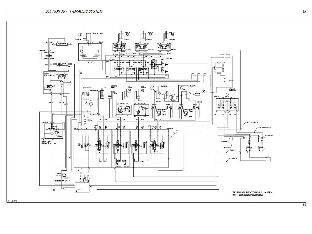
- HYDRAULIC SYSTEM
- Technical data
- Description and operation
- Introduction
- Steering system hydraulic circuit
- Steering valve
- Telescopic boom hydraulic circuit
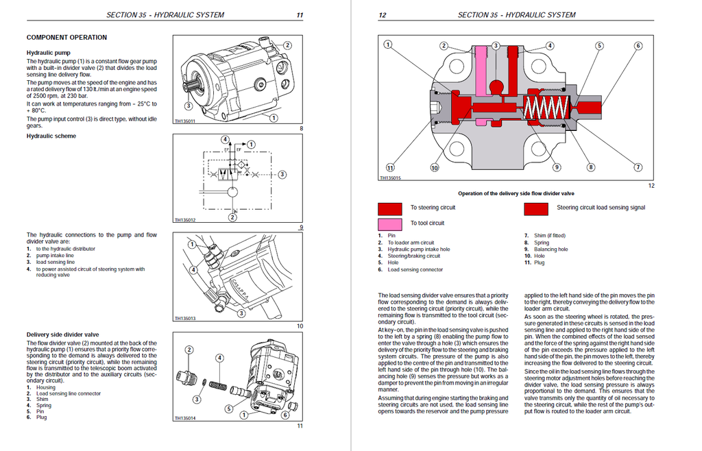
- Component operation
- Hydraulic pump
- Hydraulic scheme
- Delivery side divider valve
- Pressure reducing valve
- Front loader controls
- Power steering (OSPQ)
- Telescopic boom distributor
- Auxiliary controls distributor
- Cylinders
- Arms
- Boom removal
- Working platform
- Procedure for the calibration of the personnel carrier platform electronic controller
- Special tools
- ELECTRICAL SYSTEM
- Chapter 1 – Electrical system general
- Electrical equipment specifications
- Electrical system and fuses
- Controls and instruments
- Use of the tip-over prevention system
- Bulb replacement
- Temporary wiring repair
- Electrical system general fault finding
- Working platform
- Special tools
- Chapter 2 – Circuit diagrams
- List of connectors
- List of components
- How to use the circuit diagrams
- Diagram 1: Starting/Recharge/Warning lamps/Indicator
- Diagram 2: Transmission
- Diagram 3: Wheel alignment/Hydraulic solenoids/Brake system
- Diagram 4: Arm control
- Diagram 5: Stabiliser
- Diagram 6: Lights/Windscreen wiper
- Diagram 7: Work lamps/Roof beacon light
- Diagram 8: Tilting prevention system/Roof wiper
- Diagram 9: Sound system, heating/Electric socket/Interior lamp
- Diagram 10: Air conditioner
- Chapter 3 -- Wiring list
- Instrument panel wiring
- Cab wiring
- Front wiring
- Rear wiring
- Engine wiring
- Chapter 1 – Electrical system general