

CASE Construction WX145, WX165, WX185 Wheeled Excavator Service Manual 9-91221 English
Official Manual Overview
Master the highly complex electro-hydraulic architecture and wheeled mobility of the CASE WX145, WX165, and WX185 Hydraulic Excavators with this definitive OEM Service Manual. Moving far beyond standard structural repairs, this dealership-level volume provides uncompromising diagnostic and reconstruction protocols specifically tailored for both the wheeled undercarriage (featuring the A 6 VM 20 km/h travel oil motor and multi-disk speed-change gearboxes) and the dual-boom configurations (Monoblock and Adjustable Boom). It enforces strict parameter calibration for the machine's advanced CAN-Bus network, detailing exact programming and troubleshooting logic for the Central Unit (CU), Power Control System (PCS), and Electro-Hydraulic Controller (ESX). Whether you are electronically configuring volumetric flow limits for up to four different hammer/shear attachments via the C4 multifunction display, running deep diagnostics on the CAN1/CAN2 communication lines, or physically rebuilding the planetary gear carriers and floating-axle cylinders using exact structural fastening matrices (demanding up to 1170 Nm for critical M24x2 hardware), this guide delivers the exact factory blueprints required to restore absolute trenching precision and electronic harmony.
- Brands: CASE Construction
- Equipment Type: Wheeled Excavator
- Manuals Type: Service Manual
- Machine Model: WX145, WX165, WX185
- Serial Number: N/R
- Region: N/R
- Book Code: 9-91221
- Issued: N/R
- Language: English
- Pages: 746
- File Format: PDF (Searchable)
Core Selling Points
- Extreme Heavy-Duty Fastening Metrology: Execute hydraulic cylinder rebuilds with absolute structural certainty. This guide leaves nothing to guesswork, enforcing staggering factory torque specifications for internal components—mandating exactly 4780 Nm for the M62x2 boom cylinder hex nut, and an immense 9460 Nm for the M70x2 stick cylinder nut to prevent catastrophic piston rod separation under maximum breakout force.
- Complete CAN-Bus & ESX Network Mapping: Master the machine's digital nervous system. The manual delivers exhaustive electrical circuit diagrams mapping out the Central Unit (CU), Power Control System (PCS), and the Electro-Hydraulic Controller (ESX). It provides absolute clarity on complex wiring harnesses, detailing pin-by-pin assignments for critical connectors (X33A through X33P) to instantly trace severed lines or short circuits.
- Wheeled-Specific Drivetrain Reconstruction: Bypass standard crawler documentation and dive deep into the wheeled architecture. The literature dictates exact disassembly and measurement procedures for the steered floating axles, rigid axles, and planetary gear carriers. It extensively covers the multi-disk service brakes and the A 6 VM travel motors, ensuring flawless high-speed road travel and site mobility.
Features & Highlights
- Massive Fault Code Matrices: Transform erratic electronic behavior into a systematic diagnostic process. The text provides highly detailed fault registries for all digital modules, allowing technicians to instantly translate obscure dashboard warnings into physical repairs—whether it is tracking down a "9711 Left servo-valve, slewing, cable parting" error, a "9011 ESX checksum fault", or a PCS "8000 ERR_BROKEN_WIRE_ENGINE" failure.
- Factory Tooling & Cylinder Overhaul Blueprints: Equip your hydraulic shop with the precise OEM procedures required for fluid power restoration. The text lists the exact proprietary service tools required for teardowns, specifying the use of the 85mm hex socket insert (P/N 8488394) and dedicated bushing extraction adapters (P/N 1494090) to safely overhaul the boom, stick, and bucket cylinders without scoring the barrels.
- Advanced Attachment & Auxiliary Hydraulics: Configure the machine for specialized demolition and trenching tasks. The documentation includes highly specialized schematics for supplementary functions, detailing the exact electrical and hydraulic logic for hammer, shears, and cutter combinations, alongside precise stabilization parameters for the undercarriage levelling blade.
Problem Solver
- Resolves Paralyzing Digital Communication Drops: Stop replacing expensive electronic modules blindly. Utilizing the detailed diagnostic connector layouts (A10X4 for CAN bus 1 and A7.3X4 for CAN bus 2), mechanics can isolate data transmission failures between the display (C4) and the central electronics, permanently curing frozen screens and unresponsive joystick commands.
- Eradicates Unexplained Hydraulic Drifts & Pressure Loss: Pinpoint elusive fluid power leaks within the pilot control circuit. By referencing the ESX valve stacking and PCS valve control schematics, technicians can systematically test the Y10 proportional valve and the S113.4 pilot pressure monitoring switch, immediately resolving weak swing acceleration or sluggish boom lift.
- Cures Destructive Axle Binding & Braking Anomalies: Recover from severe wheeled undercarriage degradation. The guide systematically walks builders through the hydrostatic power steering system and the floating-axle cylinder locking mechanisms, ensuring that crawl gear solenoids (Y21.2) and pressure switches actuate flawlessly to prevent drivetrain lockups on steep gradients.
Important Pre-Purchase Advisories
- Chassis and Systems Focus: This specific OEM service manual serves as the ultimate diagnostic and structural blueprint for the excavator's complex hydraulic networks, wheeled undercarriage, electronic controllers, and cab electrical systems. While it includes basic engine wiring and integration data, deep mechanical reconstruction of the diesel engine block (such as crankshaft grinding or internal cylinder honing) requires a separate, dedicated engine repair manual.
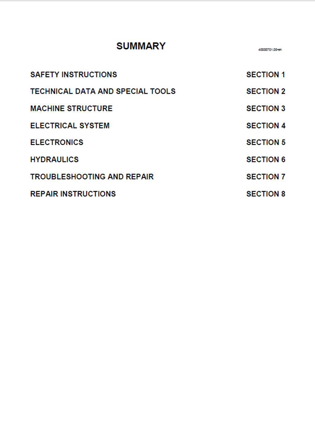
Table of Contents
- SAFETY INSTRUCTIONS
- PREFACE
- To the reader
- Handling
- Repair
- Further information material
- To the reader
- Warnings and symbols
- Organizational measures
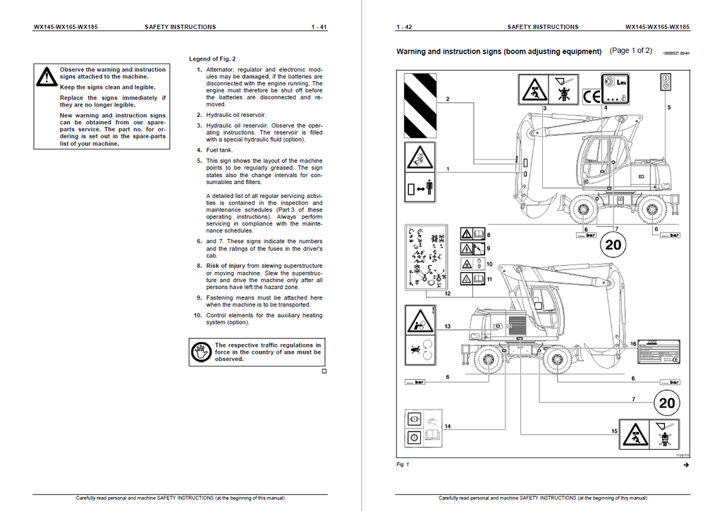
- Warning and instruction signs (mono-boom)
- PREFACE
- TECHNICAL DATA AND SPECIAL TOOLS
- Service Data General
- Foreword
- Spacers
- Service Data General
- MACHINE STRUCTURE
- MACHINE CONSTRUCTION
- Description of the machine (monoblock boom)
- Machine layout (Key to Fig. 1)
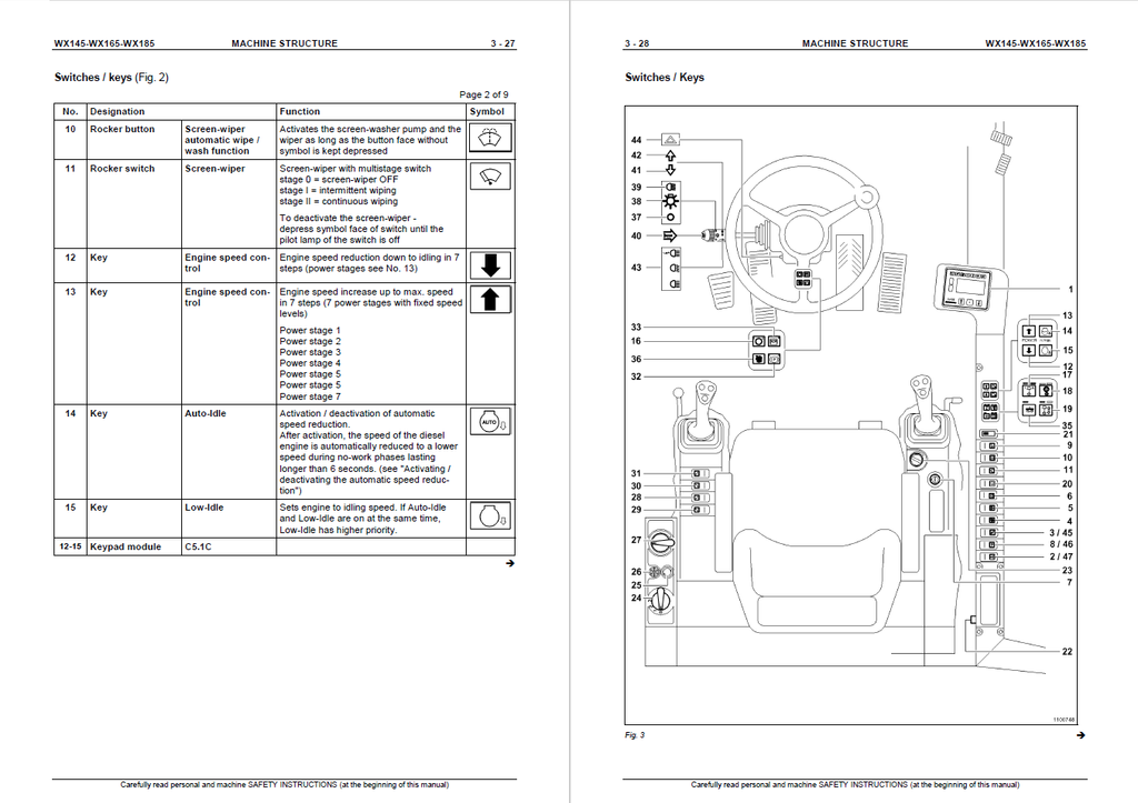
- Multifunction display
- ELECTRICAL SYSTEM
- The electrical system
- Fundamental notions
- Automotive electrical systems
- ELECTRICAL CIRCUIT DIAGRAMS, WX165, WX185, 8916247
- Table of contents, page 1, WX145
- Table of contents, page 2, WX145
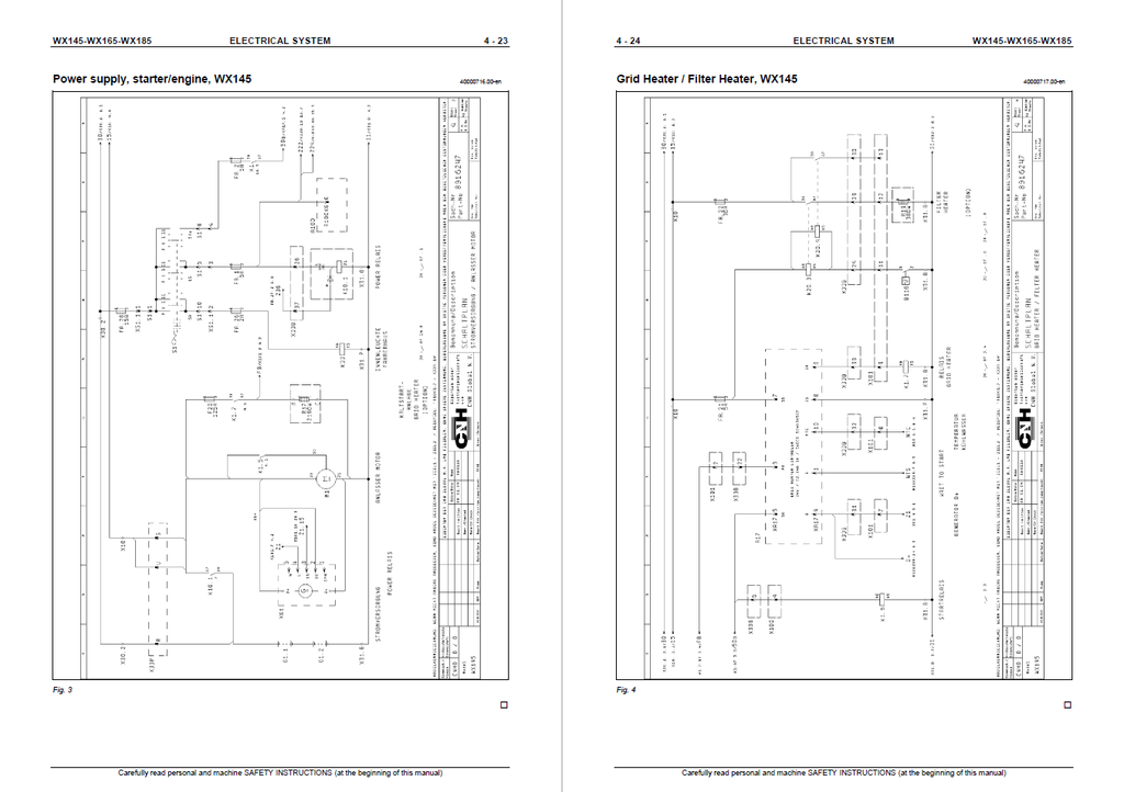
- Power supply, starter/engine, WX145
- Grid Heater / Filter Heater, WX145
- Sensor power supply, WX145
- Engine power supply - CU, WX145
- Driver's cab, voltage converter, WX145
- Driver's cab, wiper and washer, WX145
- Driver's cab, WX145
- Steering column lever switch, WX145
- Inching Function, WX145
- Lighting, WX145
- Speedometer - creep speed, WX145
- Valves - air filter control, WX145
- Service and parking brakes, WX145
- Floating axle brake, WX145
- Blower and air conditioner, WX145
- ESX coding, WX145
- ESX valve control, WX145
- ESX PCS valve control, WX145
- ESX valve stacking , WX145
- ELECTRICAL CIRCUIT DIAGRAMS, WX165, WX185, 8916248
- Table of contents, page 1, WX165/185
- Table of contents, page 2, WX165/185
- Power supply, starter/engine, WX165/185
- Grid Heater / Filter Heater, WX165/185
- Sensor power supply, WX165/185
- Tank sensor / refuelling system, WX165/185
- Pilot control shutoff, WX165/185
- PCS, WX165/185
- Switches, WX165/185
- Speed adjusting motor, WX165/185
- Engine power supply - CU, WX165/185
- Driver's cab, voltage converter, WX165/185
- Driver's cab, wiper and washer, WX165/185
- Driver's cab, WX165/185
- Steering column lever switch, WX165/185
- Inching Function, WX165/185
- Lighting, WX165/185
- Speedometer - creep speed, WX165/185
- Valves - air filter control, WX165/185
- Service and parking brakes, WX165/185
- Floating axle brake, WX165/185
- Blower and air conditioner, WX165/185
- Auxiliary heating (option)
- Hammer / shears frequency (option)
- Stabilizers / levelling blade
- ESX power supply, WX165/185
- ESX CAN1 CAN2 diagnosis, WX165/185
- ESX coding, WX165/185
- ESX PCS valve control, WX165/185
- ESX valve stacking , WX165/185
- ESX valve control, WX165/185
- ESX slewing initiator, WX165/185
- ESX pressure sensors
- CANBUS power supply, overview
- Fuses, overview
- ELECTRICAL CIRCUIT DIAGRAMS FOR SUPPLEMENTARY FUNCTIONS
- Electrical circuit diagram hammer equipment
- Electrical circuit diagram shears equipment
- Electrical circuit diagram cutter equipment
- Electrical circuit diagram hammer / shears
- Electrical circuit diagram hammer / cutter
- Electrical circuit diagram shears / cutter
- Electrical circuit diagram hammer / shears / cutter
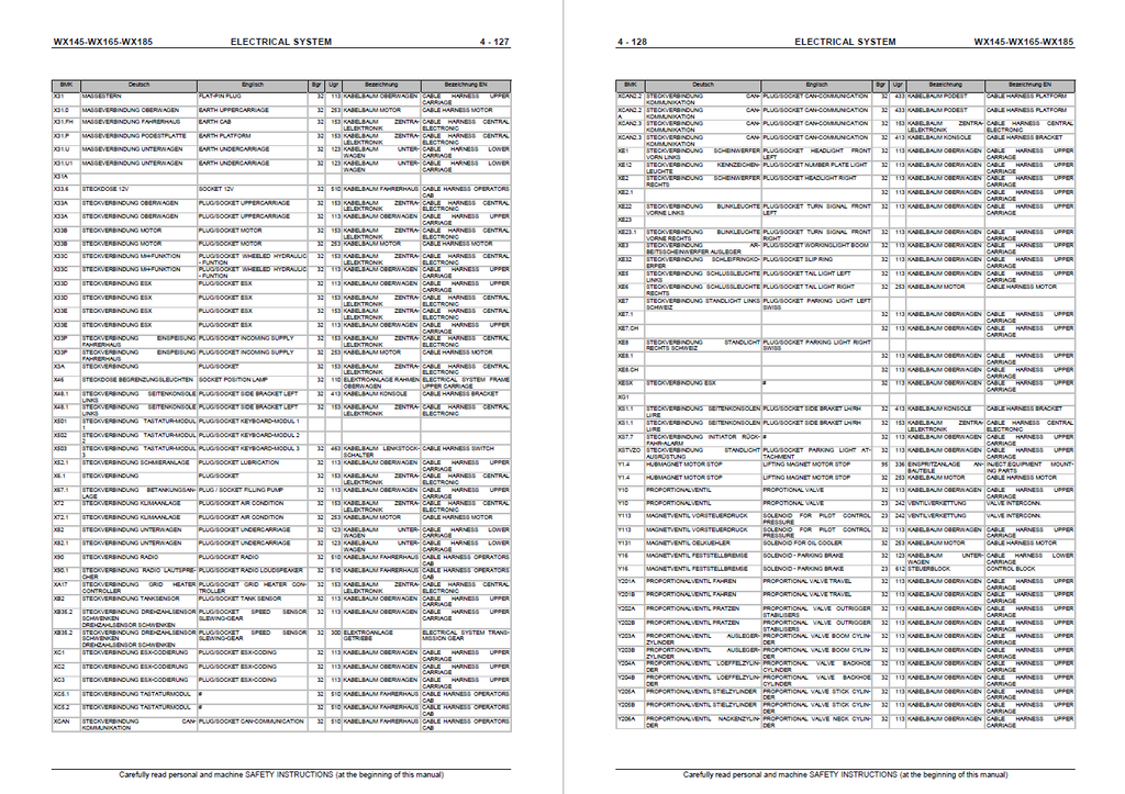
- Electrical components by code numbers
- Connector pin assignment table for connector X33A für WX145/165/185
- Connector pin assignment table for connector X33B für WX145/165
- Connector pin assignment table for connector X33B für WX185
- Connector pin assignment table for connector X33C für WX145/165/185
- Connector pin assignment table for connector X33D für WX145/165/185
- Connector pin assignment table for connector X33E für WX145/165/185
- Connector pin assignment table for connector X33P für WX145/165/185
- The electrical system
- ELECTRONICS
- CONTROL
- Introduction
- ELECTRONIC CONTROL UNIT
- Introduction
- ESX controller
- Central electronic system / Central Unit
- PCS
- Tasks
- Advantages
- Disadvantages
- Electronic control diagram
- Description
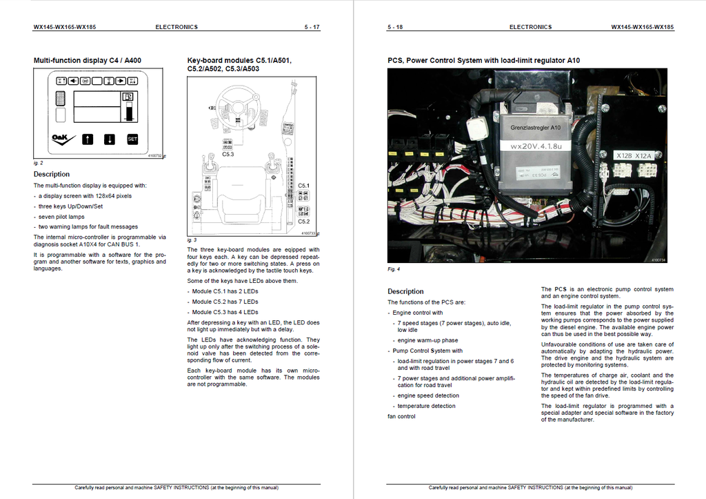
- Key-board modules C5.1/A501, C5.2/A502, C5.3/A503
- PCS, Power Control System with load-limit regulator A10
- Description
- Diagnosis socket A10X4
- Description
- Schematic
- Description
- Introduction
- PCS: POWER CONTROL SYSTEM
- Function chart and location diagram of components
- Function listing, description
- CONTROL
- HYDRAULICS
- TRAVEL CIRCUIT
- Travel circuit, schematic diagram
- Travel circuit, description
- Neutral
- Before travelling
- Forward travel
- Reverse travel
- Setting off on slopes
- BRAKING, STEERING AND FAN CIRCUIT
- Schematic diagram
- Braking, steering and fan circuit, description
- Brake system
- Superstructure
- Undercarriage
- boom cylinder circuit
- Schematic diagram without regeneration circuit
- Boom cylinder circuit without regeneration circuit, description
- Neutral
- Activation of a function
- Boom raising
- Boom lowering
- Hydraulic circuit diagram upper carriage
- Hydraulic circuit diagram WX145 boom adjusting equipment
- Hydraulic circuit diagram WX145 monoblock boom
- Hydraulic circuit diagram WX165 boom adjusting equipment
- Hydraulic circuit diagram WX165 monoblock boom
- Hydraulic circuit diagram WX185 boom adjusting equipment
- Hydraulic circuit diagram WX185 monoblock boom
- Undercarriage levelling blade A2 stabilization
- Undercarriage A4 stabilization
- Undercarriage levelling blade A2 stabilization individual control
- Undercarriage A4 stabilization individual control
- drive unit
- CONTROL BLOCK
- TRAVEL CIRCUIT
- TROUBLESHOOTING AND REPAIR
- Fault codes PCS unit
- REPAIR INSTRUCTIONS
- Foreword
- Introduction
- Removing Electronic Modules And Disconnecting Plug And Grounding Connections
- 1st Point (PCS)
- 2nd Point (CU)
- 3rd Point (ESX)
- ESX Box
- Preparations
- Removing The ESX Box
- Refitting The ESX Box
- Superstructure components
- Superstructure
- Replacing the buffers
- Removing the driver's cab
- Removing the seat
- Removing the steering column
- Removing the joysticks
- Removing the display
- Removing the ESX box
- Removing the load-limit regulator
- Gear pumps
- Single steering/brake
- Double steering/brake and grab rotation
- Displacement pump
- Valve stacking
- Removing the battery
- Removing the combined radiator
- Removing the fuel tank
- Removing the oil reservoir
- Removing the counterweight at the rear
- Removing the monoblock
- Removing the cylinders
- Dismantling the stick cylinder
- Bucket cylinder, components