

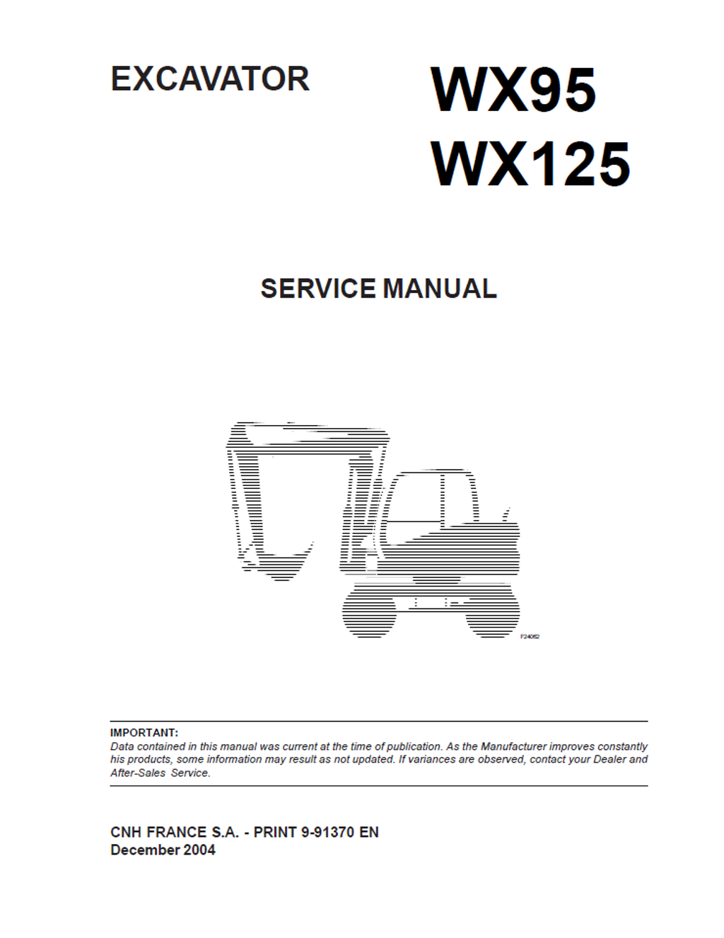
CASE Construction WX95, WX125 Wheeled Excavator Service Manual 9-91370 English
Official Manual Overview
Empower your heavy-equipment workshop with the ultimate OEM Service Manual for the CASE WX95 and WX125 Wheeled Excavators. This comprehensive blueprint goes far beyond basic structural overhauls, delivering dealership-level data for the complete drivetrain and electro-hydraulic network. It provides exhaustive teardown and calibration protocols for the DANA steering/rigid axles, Transmital slew reduction units, and the extreme 400-bar Rexroth A6VM travel motors. Furthermore, it completely demystifies the machine's electronic brain, offering pin-by-pin diagnostic matrices for the Pump Control Card and Central Unit (CU) to seamlessly troubleshoot the 3-speed transmission solenoids, crab/round steering logic, and Bosch VE4/12F mechanical injection pump timing on the IVECO F4BE diesel powerplants. Eliminate diagnostic guesswork and restore absolute trenching and high-speed mobility precision with exact factory parameters.
- Brands: CASE Construction
- Equipment Type: Wheeled Excavator
- Manuals Type: Service Manual
- Machine Model: WX95, WX125
- Serial Number: N/R
- Region: N/R
- Book Code: 9-91370
- Issued: CNH FRANCE S.A. December 2004
- Language: English
- Pages: 1016
- File Format: PDF (Searchable)
Core Selling Points
- Integrated IVECO F4BE Engine Blueprinting: Unlike standard chassis-only documentation, this master reference completely integrates the internal teardown of the F4BE0454B and F4BE0484 diesel powerplants. It dictates uncompromising fuel delivery calibration, mandating a strict 245 bar injection pressure, a highly precise 0° ± 0.5° timing adjustment for the Bosch VE4/12F mechanical pump, and absolute cylinder compression validation using the proprietary Motometer 75301430 diagnostic instrument.
- Extreme Hydraulic Cylinder Metrology: Rebuild massive fluid power components with absolute structural certainty. This guide leaves zero room for assembly error, enforcing an immense 7484 Nm tightening torque for the cylinder rod nut (utilizing the specialized 380001022 socket) and a precise 520 Nm torque for the cylinder front head to prevent catastrophic rod separation under peak digging stress.
- Advanced Steering & Transmission Circuitry: Master the highly complex wheeled mobility systems. The manual provides exhaustive electrical logic diagrams for the 4-wheel steering modes. Mechanics can physically trace crab and round steering failures by checking 24 Volt continuity across specific ECU pins (such as tracing wire 378 on connector X16-12 or checking ground on X18-13), instantly isolating faults to the steering column selector or the D5/D6 transmission solenoids.
Features & Highlights
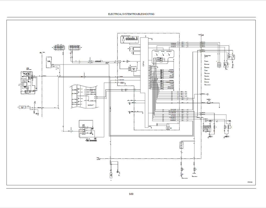
- Complete Pump Control Card Mapping: Demystify the machine’s central processing architecture. The literature includes a comprehensive pin-by-pin breakdown of the 28-pin Pump Control Card and the Machine Control Electronic Board, allowing technicians to verify inputs from the travel pedals, brake pressure switches, and joysticks without blind testing.
- Dynamic Hydraulic Pressure Calibration: Restore maximum trenching and travel performance using factory fluid parameters. The text provides exact benchmark settings, requiring technicians to calibrate the main relief valves to 380 ± 10 bar, the heavy-duty translation circuits to 400 ± 10 bar, and verify the brake pedal valve's pressure differential at exactly 3.5 bar.
- Proprietary Undercarriage Tooling Registry: Equip your heavy-duty workshop with the exact OEM instruments required for drivetrain overhauls. The documentation strictly mandates the use of tool 75301742 to verify steering arm flatness prior to cross-tightening bolts to 298 Nm, and tool 75301760 to mathematically evaluate multi-disc brake wear limits.
Problem Solver
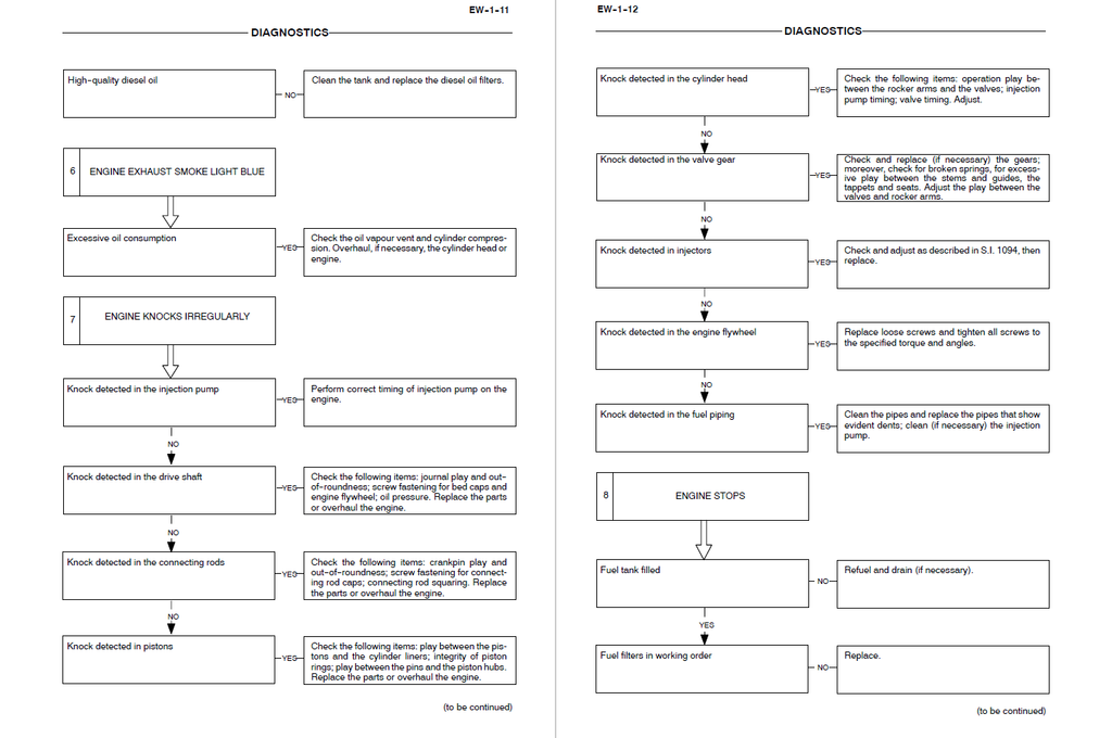
- Eradicates Paralyzing "Poti Diesel" & Engine Overloads: Stop throwing replacement parts at erratic engine behavior. Utilizing the on-board display diagnostics, mechanics can actively monitor the actuator potentiometer (verifying voltage ranges from 0.8V to 5V) and isolate "Prop main pump" or "Diesel sensor" fault codes directly to short-circuited R1/R2 proportional solenoids.
- Resolves Severe Undercarriage Binding & Braking Anomalies: Navigate the hydrostatic travel circuit scientifically. By referencing the detailed hydraulic flowcharts, technicians can systematically test the P4/P5 travel pressure switches (set at 3 bar) and the P2 brake switch, instantly resolving drivetrain lockups or the failure of the 3rd hydraulic speed engagement.
- Cures Unexplained Boom & Arm Drifts: Pinpoint elusive structural wear and fluid leaks. Machinists are provided with absolute geometric tolerance tables for all articulation points, mandating the replacement of bushings if the clearance exceeds strict physical limits (e.g., condemning the 1st arm foot if the pin-to-bushing gap surpasses 0.434 mm on the WX95 or 0.467 mm on the WX125).
Important Pre-Purchase Advisories
- Comprehensive All-In-One Literature: This specific Service Manual is a highly valuable asset as it is a "hybrid" volume. It not only covers the complete hydraulic, electrical, and structural repair of the WX95 and WX125 excavators but also contains the full, unabridged "Engine Overhaul" section for the F4BE04 series diesel engines. You do not need to purchase a separate engine repair manual to perform deep block machining or injection pump timing.
Table of Contents
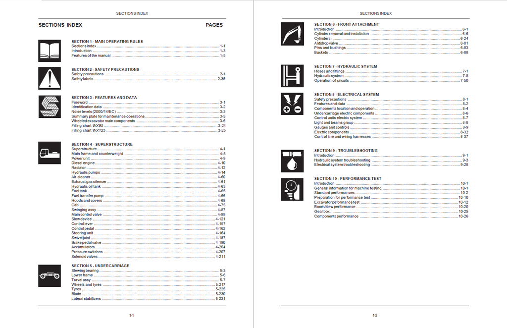
- MAIN OPERATING RULES
- Sections index
- Introduction
- Foreword
- Manual handling
- Symbols and indications
- Features of the manual
- Manual composition
- Brief information for manual consultation
- SAFETY PRECAUTIONS
- Safety precautions
- Safety labels
- FEATURES AND DATA
- Foreword
- Identification data
- Noise levels (2000/14/EC)
- Summary plate for maintenance operations
- Wheeled excavator main components
- Filling chart WX95
- Filling chart WX125
- SUPERSTRUCTURE
- Superstructure
- Main frame and counterweight
- Power unit
- Diesel engine
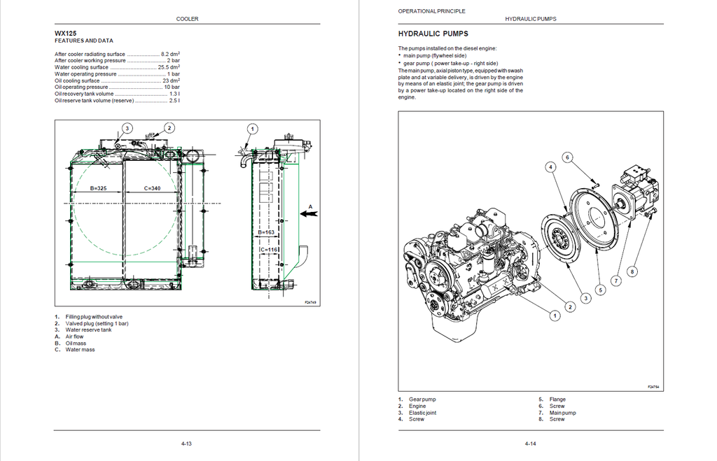
- Radiator
- Hydraulic pumps
- Air cleaner
- Exhaust gas silencer
- Hydraulic oil tank
- Fuel tank
- Fuel transfer pump
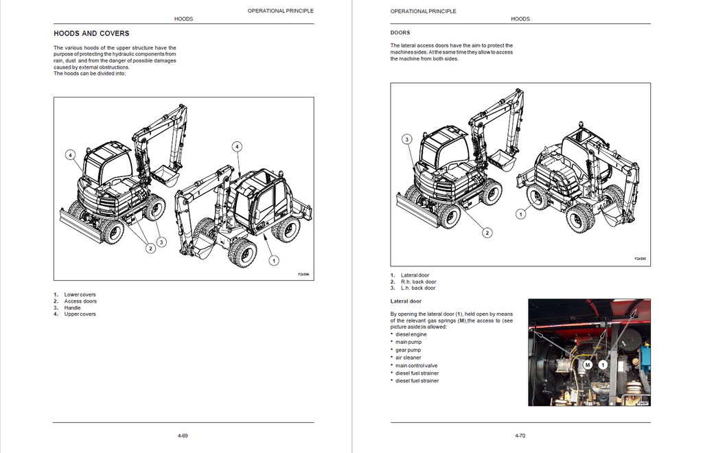
- Hoods and covers
- Cab
- Swinging assy
- Main control valve
- Slew device
- Slew hydraulic motor
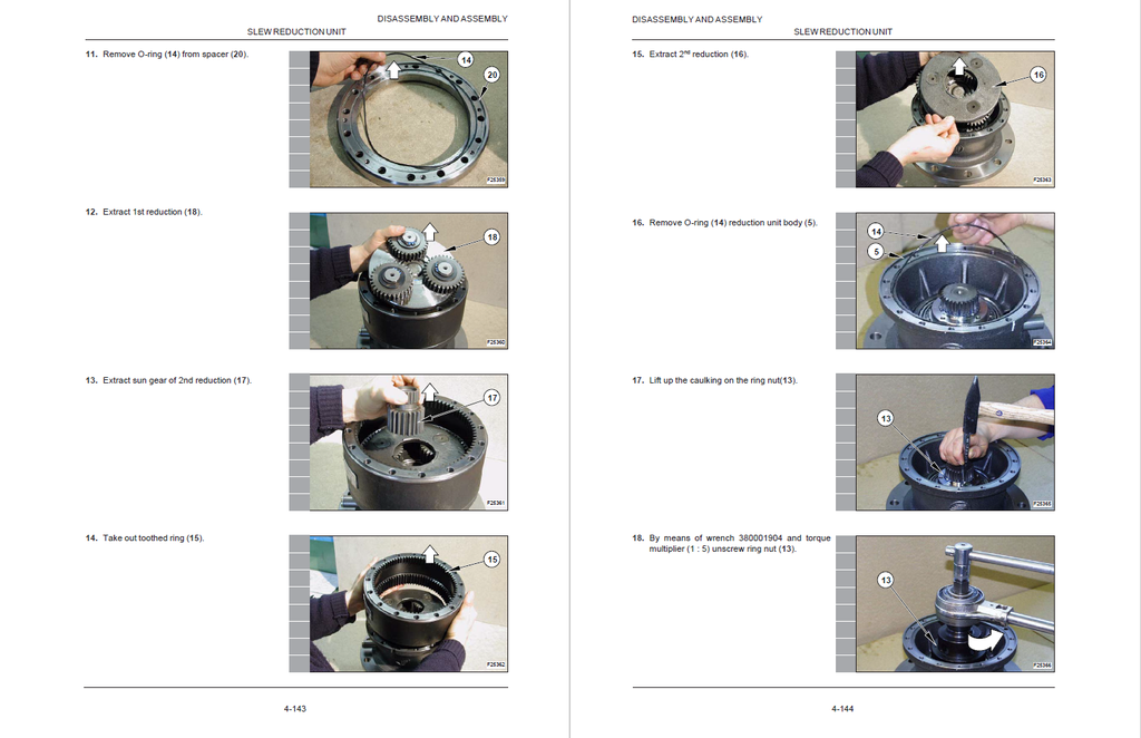
- Slew reduction unit
- Control lever
- Control pedal
- Steering unit
- Swivel joint
- Features and data
- Brake pedal valve
- Accumulators
- Pressure switches
- Solenoid valves
- UNDERCARRIAGE
- Slewing bearing
- Lower frame
- Travel assy
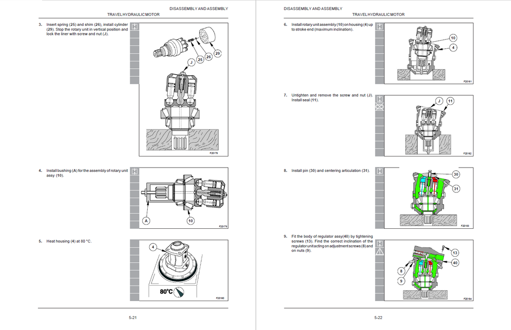
- Travel hydraulic motor
- Speeds gear box
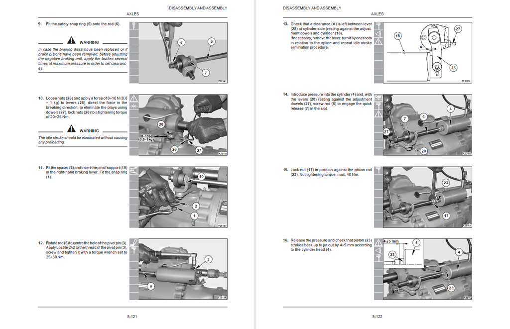
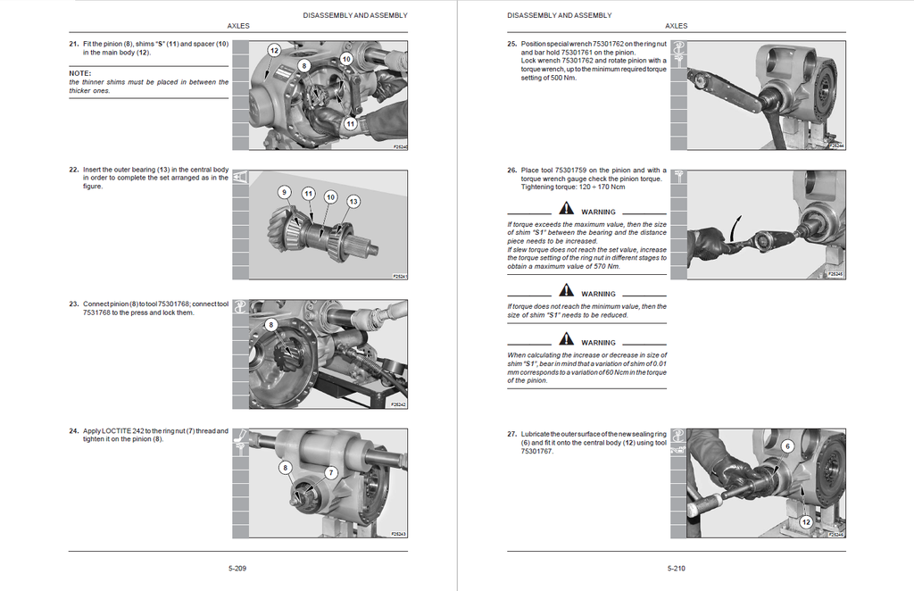
- Steering axles: Front and rear
- Rigid rear axle
- Drive shaft
- Wheels and tyres
- Tyres
- Blade
- Lateral stabilizers
- FRONT ATTACHMENT
- Introduction
- Cylinder removal and installation
- Cylinders
- WX95 Bucket cylinder
- Arm cylinder
- Positioning cylinder
- Boom cylinder
- WX125 Bucket cylinder
- Arm cylinder
- Positioning cylinder
- Boom cylinder
- Antidrop valve
- Pins and bushings
- Buckets
- HYDRAULIC SYSTEM
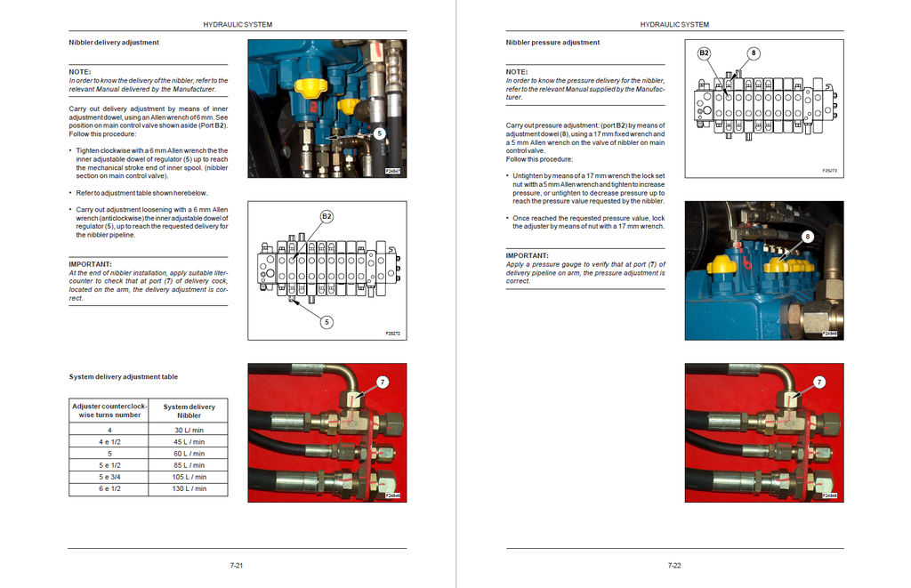
- Hoses and fittings
- Hydraulic system
- Operation of circuits
- ELECTRICAL SYSTEM
- Safety precautions
- Features and data
- Components location and operation
- Undercarriage electric components
- Control units electric system
- Light and beams group
- Gauges and controls
- Dashbboards
- Control levers
- Switches and control lights panel
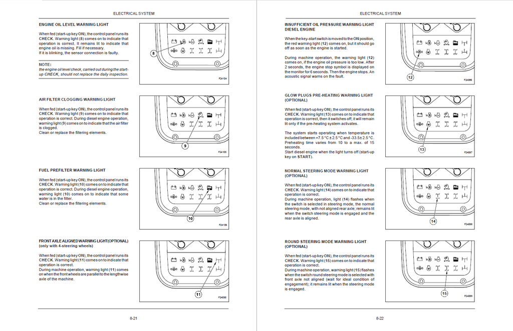
- Switches and warning lights
- Monitor panel
- Key start switch
- Left control lever
- Right-hand control lever
- Control panel and switches
- Machine control card
- Pump control card
- Electric components
- Control line and wiring harnesses
- Controls on consoles
- Controls for side panel switches
- Anti-tilting check control line
- Working lights control line
- Traffic beams control line
- Steering column controls
- TROUBLESHOOTING
- Introduction
- Hydraulic system troubleshooting
- Electrical system troubleshooting
- PERFORMANCE TEST
- Introduction
- General information for machine testing
- Standard performances
- WX95 Table of excavator standard performances
- Hydraulic components standard performance
- Main pump p-q curve
- WX125 Table of excavator standard performances
- Hydraulic components standard performance
- Main pump p-q curve
- Preparation for performance test
- Excavator peformance test
- Engine performance
- Slew performance
- Front attachment performance
- Control levers
- Boom/slew performance
- Combined slew/boom test
- Steering
- Brakes system
- Gear box
- Gear box pressure check
- Components performance
- Overpressure valve and pilot control line
- Overpressure relief valves
- Drive shaft
- WX95 Hydraulic pumps
- WX125 Hydraulic pumps
- Travel motor
- ENGINES F4BE0454B F4BE0484D F4BE0484E OVERHAUL
- Engines F4BE0484
- Coding of source engines
- Main engines features
- Torque and rating features
- General engines features F4BE0454
- Assembling engines play F4BE0454 -specifications
- General engines features F4BE0484
- Assembling engines play F4BE0484 -specifications
- Tightening torque
- Tools
- Graphic indications and symbols
- General remarks
- Description of main mechanic engine components
- Crankcase
- Drive shaft
- Drive shaft seal rings
- Connecting rods
- Pistons
- Distributing shaft
- Valve control
- Cylinder head
- Valves and valve seats
- Valve guides
- Engine flywheel
- Auxiliary component drive
- Lubrication
- Heat exchanger
- Oil pump
- Oil sump
- Oil vapour recirculation
- Cooling
- Water pump
- Mechanic injection feeding system
- Fuel prefilter
- Fuel filter
- Mechanic fuel pump
- Injection assembly
- Engine bench-overhaul
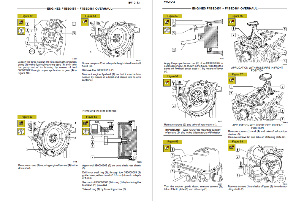
- Disassembling the engine
- Removing the front seal ring
- Removing the injection pump
- Removing the rear seal ring
- Removing the rocker arm assembly and cylinder head
- Repair work on cylinder cluster
- Checks and measurements
- Checking the surface supporting the head on the cylinder cluster
- Valve gear
- Distributing shaft
- Checking the eccentric lift and the pin alignment
- Bushings
- Replacing the bushings
- Tappets
- Mounting the tappets – Distributing shaft
- Drive shaft
- Measuring the journals and crankpins
- Replacing the oil pump drive gears
- Mounting the main bearings
- Measuring the journal assembling play
- Checking the drive shaft shoulder play
- Connecting rod-piston assembly
- Measuring the piston diameter
- Gudgeon pins
- Conditions for correct pin/piston matching
- Piston rings
- Connecting rods
- Bushings
- Checking the connecting rods
- Checking the torsion
- Checking the flexion
- Connecting rod-piston match
- Mounting the piston rings
- Mounting the connecting rod/piston assemblies in the cylinder liners
- Measuring the crankpin assembling play
- Checking piston protrusion
- Valve gear
- Distribution gearbox case
- Valve timing
- Injection pump – 1st phase
- Timing
- Flywheel cover case
- Mounting the rear seal ring
- Engine flywheel
- Replacing the engine flywheel ring gear
- Injection pump – 2nd phase
- Mounting the injection pump – 2nd phase
- Mounting the oil and water pumps
- Monting the front seal ring
- Mounting the oil sump
- Mounting the water / oil heat exchanger
- Cylinder head
- Removing the valves
- Checking the cylinder head supporting surface
- Checking the cylinder head water seal
- Valves
- Valve descaling, check and grinding
- Checking the play between the valve stem, valve guide and valve centring
- Valve guide
- Valve seat reconditioning - replacement
- Valve springs