

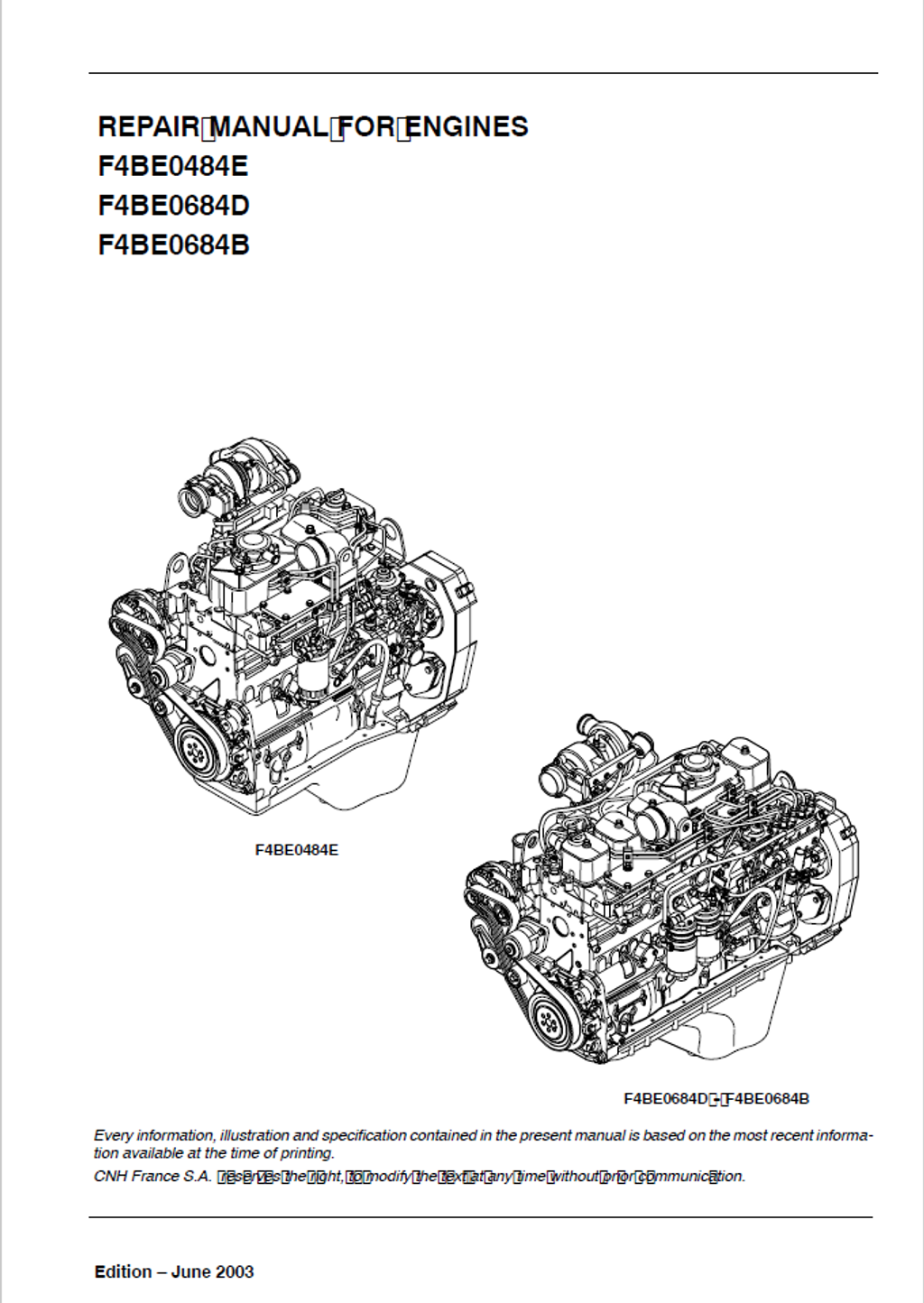
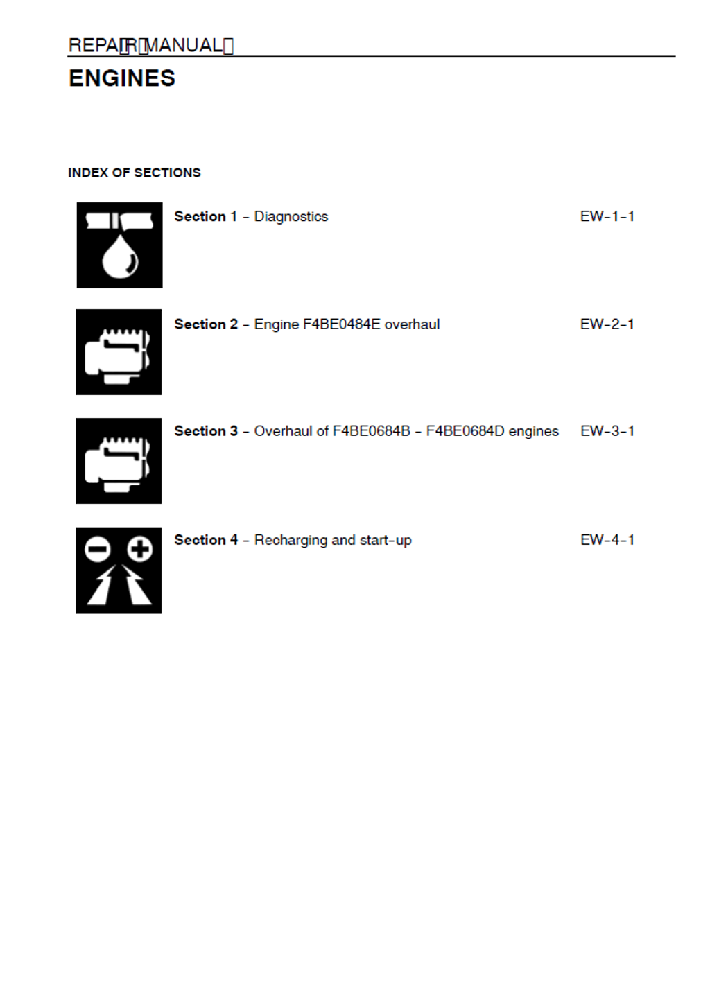
Iveco Motors / FPT Industrial F4BE0484E, F4BE0684D, F4BE0684B Diesel Engine Repair Manual 9-88960 English
Official Manual Overview
Take absolute command over the Tier 2 compliant 3.9-liter F4BE0484E and the massive 5.9-liter F4BE0684D / F4BE0684B Diesel Engines with this definitive OEM Repair Manual published under the CNH/CASE Construction architecture. Specifically engineered for heavy-duty earthmovers, this master reference completely breaks down the mechanical disparities across the lineup—from calibrating the 4-cylinder's rotary injection pump to fine-tuning the 6-cylinder's in-line injection system. It enforces absolute factory metrology, dictating a strict 245 bar injection pressure baseline, demanding precise valve seat resurfacing at exact 45° (exhaust) and 60° (intake) angles, and mandating the use of the specialized Motometer 75301430 adapter for absolute cylinder compression validation. Whether you are overhauling the specific HOLSET HX25W or HX35W turbochargers, or executing deep physical teardowns of the non-structural block, this uncompromising guide delivers the exact factory blueprints required to eradicate diagnostic guesswork and restore peak 118 kW industrial efficiency.
- Brands: Iveco Motors / FPT Industrial / CASE Construction
- Equipment Type: Diesel Engine
- Manuals Type: Repair Manual
- Machine Model: F4BE0484E, F4BE0684D, F4BE0684B
- Serial Number: N/R
- Region: N/R
- Book Code: 9-88960
- Issued: CNH France S.A. June 2003
- Language: English
- Pages: 196
- File Format: PDF (Searchable)
Core Selling Points
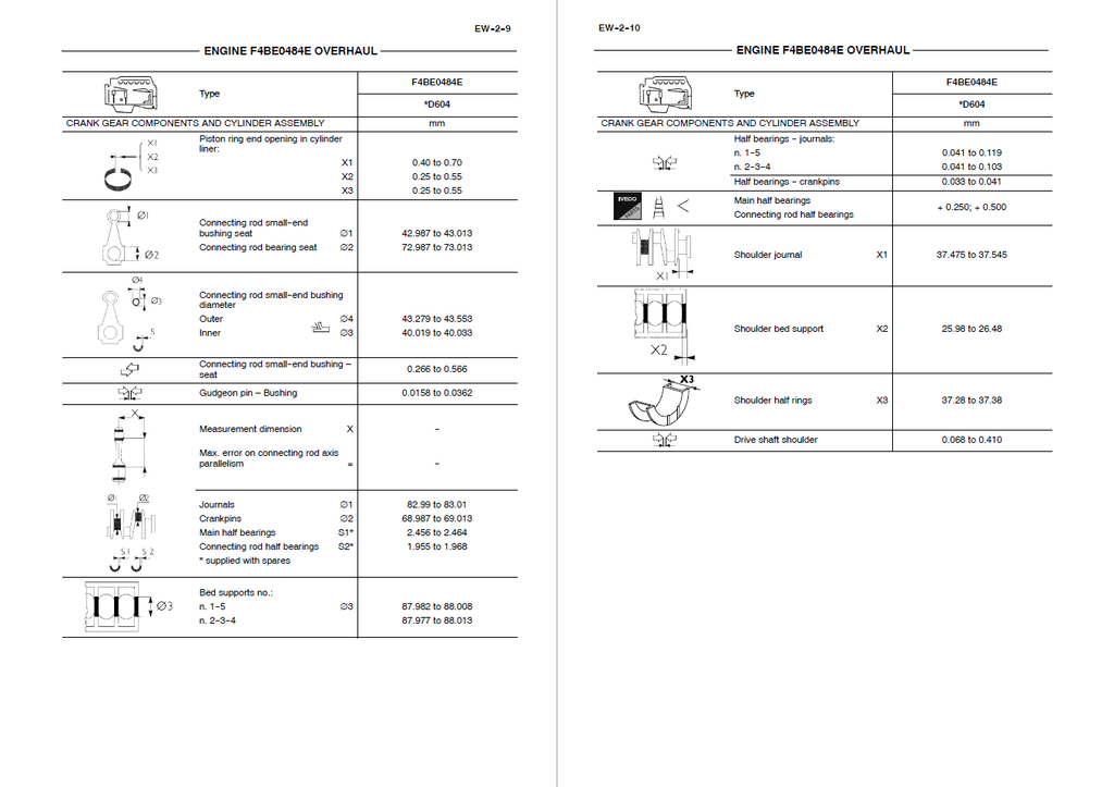
- Micro-Precision Cylinder Metrology: Rebuild the combustion chamber with uncompromising mathematical standards. This manual dictates exact dimensional limits for the cylinder block, enforcing a rigid 102.01 to 102.03 mm baseline for the cylinder liners and establishing a highly controlled 0.215 to 0.253 mm tolerance for the piston-to-liner clearance, ensuring absolute compression integrity under heavy earthmoving loads.
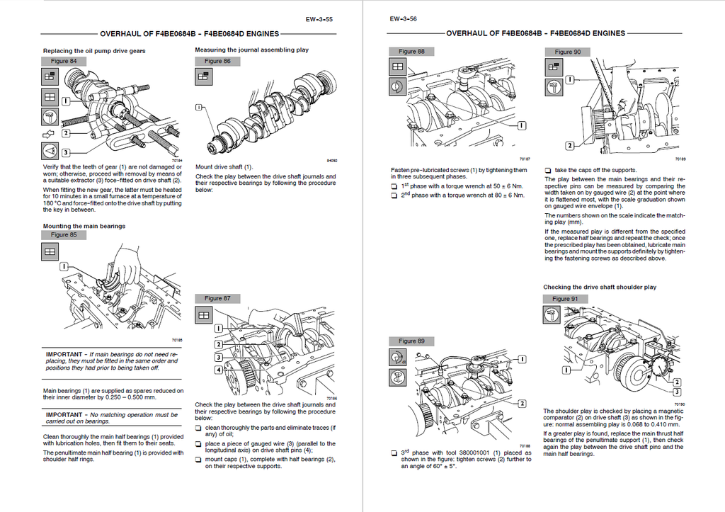
- Rotational Mass Blueprinting: Take the guesswork out of the bottom-end overhaul. The documentation provides exhaustive parameters for the drive shaft assembly, specifying strict +0.250 mm and +0.500 mm reduction machining classes. It further demands mechanics verify the drive shaft shoulder play within a tight 0.068 to 0.410 mm window, guaranteeing perfect structural stability.
- Strict Component Thermal Fitting: Master the assembly of heavy-interference components. Unlike basic service guides, this reference mandates specialized temperature controls during reconstruction, explicitly instructing technicians to heat the oil pump drive gear in a furnace at precisely 180°C for 10 minutes prior to force-fitting it onto the drive shaft, preventing stress fractures and premature gear shear.
Features & Highlights
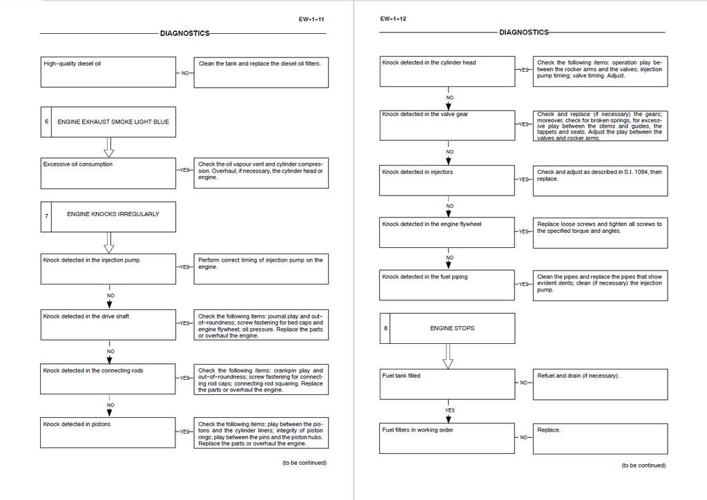
- 12-Stage Diagnostic Logic Matrices: Transform complex troubleshooting into a systematic science. The literature includes a dozen dedicated YES/NO flowchart trees covering critical failures (from "Engine exceeds max revs" to "Engine won't stop"). It guides technicians to rapidly trace faults down to a failed cut-off electromagnet, an improperly adjusted L.D.A. device, or a malfunctioning thermal starter.
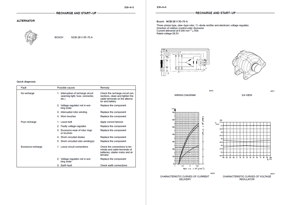
- Heavy-Duty Electrical Bench Testing: Bypass the parts cannon on auxiliary electronics. The manual provides direct diagnostic paths, wiring diagrams, and characteristic curves for the engine-mounted Bosch 24V-4kW starter motor and the Bosch NCBI 28V 35-70A alternator, allowing builders to isolate insufficient dragging torque directly to short-circuited field windings or worn brushes.
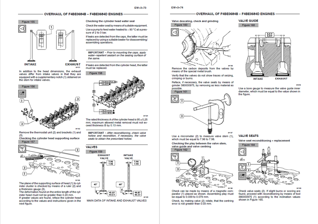
- Dynamic Valve Spring Load Validation: Evaluate overhead mechanisms utilizing factory tooling standards. Using the dedicated 380000976 load-check unit, machinists are instructed to physically verify spring elasticity—demanding exactly 329 N of resistance at a 49.02 mm compression height, and peaking at 641 N when compressed to 38.20 mm.
Problem Solver
- Resolves Severe Upper-End Clatter: Prevent hidden valvetrain destruction and restore breathing efficiency. Machinists are provided with absolute geometric data for the cylinder head guides, mandating the internal guide diameter remain between 8.019 and 8.039 mm, while strictly enforcing a 0.052 to 0.092 mm operating clearance between the valve stem and guide to cure excessive oil consumption and valve float.
- Eradicates Destructive Engine Knocking: Differentiate between upper-head noise and catastrophic lower-block failure instantly. Specialized flowcharts equip the technician to isolate the root cause, sequentially checking crankpin play, connecting rod squaring, and bed cap torque integrity before needlessly condemning the rotary or in-line injection pump.
- Cures Phantom Power Loss & Black Smoke: Stop throwing replacement parts at erratic running engines. The guide systematically walks mechanics through the fuel delivery network, from testing the automatic advance variator to bench-adjusting the injection pump's peak adjusting-screw, permanently resolving fuel over-delivery and atomization failures.
Important Pre-Purchase Advisories
- Dedicated Engine Overhaul Blueprint: This specific manual is exclusively focused on the deep mechanical reconstruction of the CASE/CNH F4BE0484E (4-cylinder) and F4BE0684D / F4BE0684B (6-cylinder) Tier 2 diesel engines. It extensively covers engine block machining, rotational assembly tolerances, mechanical pump calibration, and engine-mounted electrics. For diagnostics relating to the host earthmover's hydraulic system, cabin CAN-bus electronics, or transmission teardowns, a separate machine-specific chassis manual is required.
Table of Contents
- Diagnostics
- Engine won’t start
- Engine overheats
- Engine lacks power and works erratically
- Engine exhaust smoke black or dark grey
- Engine exhaust smoke grey (verging on white)
- Engine exhaust smoke light blue
- Engine knocks irregularly
- Engine stops
- Engine exceeds max. revs number
- Excessive or insufficient oil pressure
- Excessive fuel consumption
- Engine won’t stop
- Engine F4BE0484E Overhaul
- Engine
- Coding of source engines
- Main engine features
- General engine features
- Assembling play - specifications
- Tightening torque
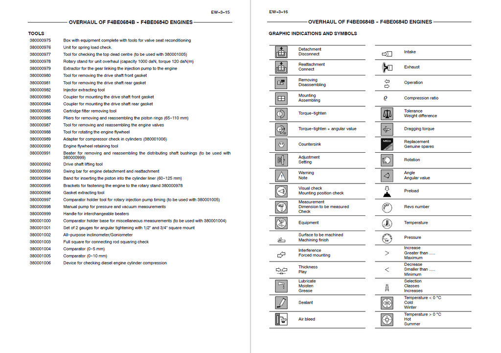
- Tools
- Graphic indications and symbols
- General remarks
- Description of main mechanic engine components
- Crankcase
- Drive shaft
- Drive shaft seal rings
- Connecting rods
- Pistons
- Distributing shaft
- Valve control
- Cylinder head
- Valves and valve seats
- Valve guides
- Engine flywheel
- Auxiliary component drive
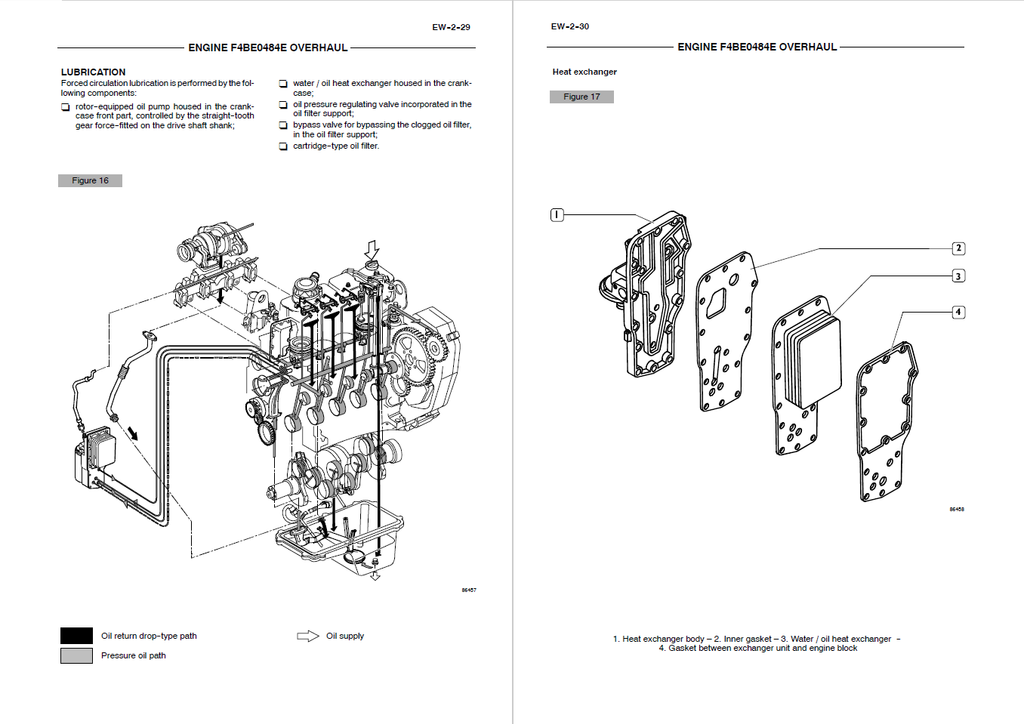
- Lubrication
- Heat exchanger
- Oil pump
- Oil sump
- Oil vapour recirculation
- Cooling
- Water pump
- Mechanic injection feeding system
- Fuel prefilter
- Fuel filter
- Mechanic fuel pump
- Injection assembly
- Engine bench-overhaul
- Disassembling the engine
- Replacing the seal ring
- Removing the injection pump
- Removing the rocker arm assembly
- Repair work on cylinder cluster
- Checks and measurements
- Checking the surface supporting the head on the cylinder cluster
- Valve gear
- Distributing shaft
- Checking the eccentric lift and the pin alignment
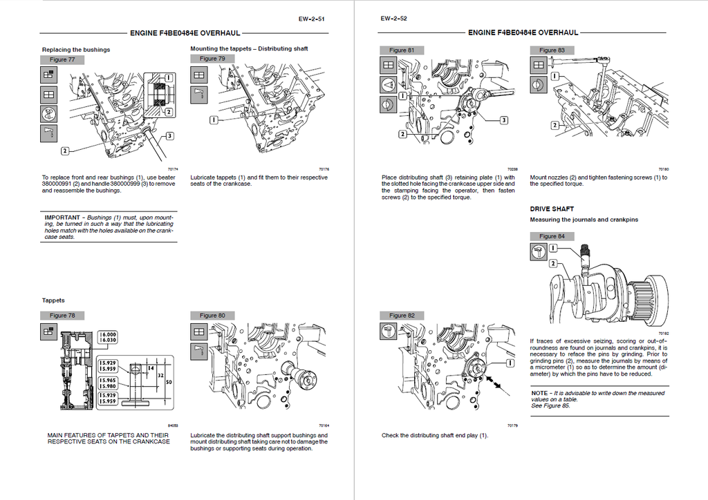
- Bushings
- Replacing the bushings
- Tappets
- Mounting the tappets – Distributing shaft
- Drive shaft
- Measuring the journals and crankpins
- Replacing the oil pump drive gears
- Mounting the main bearings
- Measuring the journal assembling play
- Checking the drive shaft shoulder play
- Connecting rod-piston assembly
- Pistons
- Measuring the piston diameter
- Gudgeon pins
- Conditions for correct pin/piston matching
- Piston rings
- Connecting rods
- Bushings
- Checking the connecting rods
- Checking the torsion
- Checking the flexion
- Mounting the connecting rod-piston assembly
- Connecting rod-piston match
- Mounting the piston rings
- Mounting the connecting rod/piston assemblies in the cylinder liners
- Measuring the crankpin assembling play
- Checking piston protrusion
- Valve gear
- Distribution gearbox case
- Valve timing
- Injection pump – 1st phase
- Timing
- Flywheel cover case
- Engine flywheel
- Replacing the engine flywheel ring gear
- Injection pump – 2nd phase
- Mounting the injection pump – 2nd phase
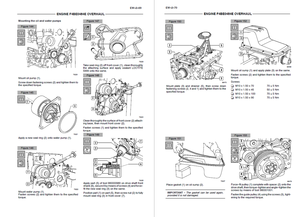
- Mounting the oil and water pumps
- Mounting the water / oil heat exchanger
- Cylinder head
- Removing the valves
- Checking the cylinder head supporting surface
- Checking the cylinder head water seal
- Valves
- Valve descaling, check and grinding
- Checking the play between the valve stem, valve guide and valve centring
- Valve guide
- Valve seats
- Valve seat reconditioning - replacement
- Valve springs
- Mounting the cylinder head
- Reattaching the cylinder head
- Rocker arm assembly
- Mounting the injectors
- Replacing the injectors
- Removal
- Reassembling
- Adjusting the tappets
- Removal
- Reassembling
- Rocher arm removal/refitting
- Valve timing
- Overhaul of F4BE0684B - F4BE0684D Engines
- Engine F4BE0684B
- Engine coding
- Main engine features
- Assembling play - specifications
- Tightening torque
- Tools
- Graphic indications and symbols
- General remarks
- Description of main mechanic engine components
- Crankcase
- Drive shaft
- Drive shaft seal rings
- Connecting rods
- Pistons
- Distributing shaft
- Valve control
- Cylinder head
- Valves and valve seats
- Valve guides
- Engine flywheel
- Auxiliary component drive
- Lubrification
- Heat exchanger
- Oil pump
- Oil sump
- Oil vapour recirculation
- Cooling
- Water pump
- Mechanic injection feeding system
- Fuel prefilter
- Fuel filters
- Mechanic fuel pump
- Injection assembly
- Engine bench-overhaul
- Disassembling the engine
- Replacing the seal ring
- Removing the injection pump
- Removing the rocker arm assembly
- Repair work on cylinder cluster
- Checks and measurements
- Checking the surface supporting the head on the cylinder cluster
- Valve gear
- Distributing shaft
- Checking the eccentric lift and the pin alignment
- Bushings
- Replacing the bushings
- Tappets
- Mounting the tappets – Distributing shaft
- Drive shaft
- Measuring the journals and crankpins
- Replacing the oil pump drive gears
- Mounting the main bearings
- Measuring the journal assembling play
- Checking the drive shaft shoulder play
- Connecting rod-piston assembly
- Pistons
- Measuring the piston diameter
- Gudgeon pins
- Conditions for correct pin/piston matching
- Piston rings
- Connecting rods
- Bushings
- Checking the connecting rods
- Checking the torsion
- Checking the flexion
- Mounting the connecting rod-piston assembly
- Connecting rod-piston match
- Mounting the piston rings
- Mounting the connecting rod/piston assemblies in the cylinder liners
- Measuring the crankpin assembling play
- Checking piston protrusion
- Valve gear
- Distribution gearbox case
- Valve timing
- Injection pump – 1st phase
- Timing
- Flywheel cover case
- Engine flywheel
- Replacing the engine flywheel ring gear
- Injection pump – 2nd phase
- Mounting the injection pump – 2nd phase
- Mounting the oil and water pumps
- Mounting the oil sump
- Mounting the water/oil heat exchanger
- Cylinder head
- Removing the valves
- Checking the cylinder head supporting surface
- Checking the cylinder head water seal
- Valves
- Valve descaling, check and grinding
- Checking the play between the valve stem, valve guide and valve centring
- Valve guide
- Valve seats
- Valve seat reconditioning - replacement
- Valve springs
- Mounting the cylinder head
- Reattaching the cylinder head
- Rocker arm assembly
- Mounting the injectors
- Replacing the injectors
- Removal
- Reassembling
- Adjusting the tappets
- Rocker arm removal/reassembling
- Removal
- Reassembling
- Valve timing
- Recharge and start-up
- Starter motor
- Quick diagnosis
- Bosch 24 V - 4 kW
- Alternator
- Starter motor