

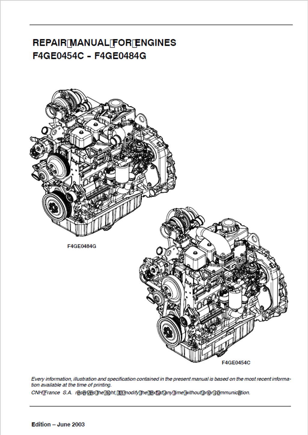

Iveco Motors / FPT Industrial F4GE0454C, F4GE0484G Diesel Engine Repair Manual 9-88900 English
Official Manual Overview
Take absolute command over the 4.5-liter, 4-cylinder F4GE0454C and F4GE0484G Diesel Engines with this definitive OEM Repair Manual published under the CNH/CASE Construction architecture. Engineered strictly for master engine builders and heavy-duty machinists, this volume obliterates diagnostic guesswork, delivering uncompromising, surgical reconstruction protocols specifically for these earthmover powerplants. It demands absolute mathematical certainty, dictating a strict 104 mm cylinder liner bore baseline and enforcing rigorous bottom-end metrology with precisely defined 0.250 mm and 0.500 mm crankshaft reduction classes. Furthermore, it establishes immense structural fastening matrices—requiring exactly 200 ± 20 Nm of torque for the heavy-duty M16 structural hardware—and provides the exact factory tuning parameters for the Bosch VE4 / 12 F 1100 L rotary injection pump, specifying a precise 245 bar injection pressure threshold. From turbocharger (HOLSET HX25W) diagnostics to exact valve seat angle resurfacing (45° and 60°), this master reference provides the exact factory blueprint required to eradicate power loss and restore peak 82 kW combustion efficiency.
- Brands: Iveco Motors / FPT Industrial / CASE Construction
- Equipment Type: Diesel Engine
- Manuals Type: Repair Manual
- Machine Model: F4GE0454C, F4GE0484G
- Serial Number: N/R
- Region: N/R
- Book Code: 9-88900
- Issued: Copyright CNH France S.A. June 2003
- Language: English
- Pages: 116
- File Format: PDF (Searchable)
Core Selling Points
- Top-End Metrology & Teardown Protocol: Execute cylinder head overhauls with absolute mathematical certainty. The manual dictates maximum material removal limits—strictly condemning the cylinder head if machining exceeds the 0.13 mm threshold—and enforces a rigid 0.052 to 0.092 mm clearance between the valve stem and guide to restore flawless combustion chamber sealing.
- Complex Angular Fastening Sequences: Secure the engine block against extreme internal pressures. Machinists are instructed to utilize a highly specific, staggered baseline torque for the cylinder head (50 Nm, 40 Nm, and 70 Nm depending on exact screw length), followed sequentially by two brutal 90-degree rotational stretch phases to achieve perfect bolt plasticity.
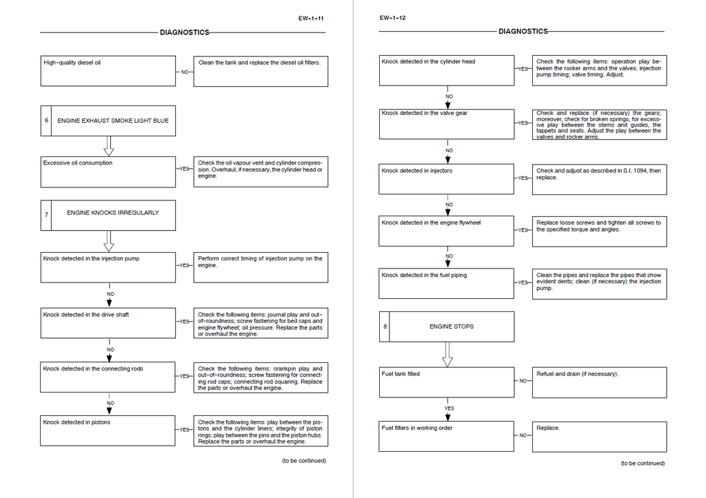
- Extensive Symptom-Based Logic Trees: Transform diagnostic guesswork into a systematic science. The literature provides 12 dedicated fault matrices (covering anomalies from "Engine exceeds max. revs" to "Exhaust smoke light blue"), utilizing rigid YES/NO pathways to rapidly isolate failures down to a specific pressure control valve or a scored injection pump distributing plunger.
Features & Highlights
- Rotational Mass Blueprinting: Command the exact micrometer tolerances for the bottom-end assembly. The documentation strictly dictates main bearing clearances between 0.041 and 0.119 mm, and specifies a highly controlled 0.068 to 0.410 mm drive shaft shoulder play, guaranteeing perfect crankshaft stability under heavy industrial loads.
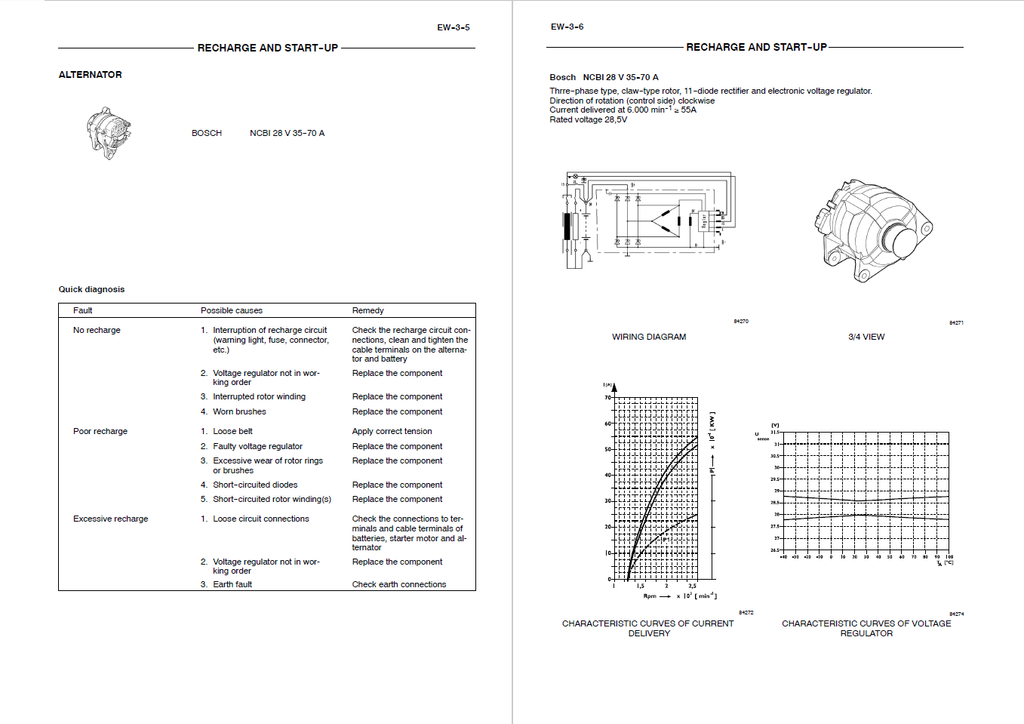
- Heavy-Duty Charging & Starting Schematics: Dive directly into the auxiliary electrical units. The guide supplies complete internal wiring diagrams, characteristic delivery curves, and bench-test procedures for both the Bosch 24V-4kW starter motor and the Bosch NCBI 28V 35-70A alternator, preventing unnecessary and expensive part replacements.
- Micro-Precision Valvetrain Calibration: Evaluate the overhead mechanisms utilizing factory tooling standards. The text requires technicians to measure valve spring elasticity under load (dictating exactly 329 N at a 49.02 mm height and 641 N at 38.20 mm compression) while enforcing a tight 0.025 to 0.063 mm operating play between the rocker arms and their central shaft.
Problem Solver
- Resolves Phantom White Smoke & Compression Loss: Stop throwing parts at hard-starting engines. The manual mandates exact cylinder compression tests utilizing the specific Motometer 75301430 adapter, requiring mechanics to verify the exact piston protrusion (0.28 to 0.52 mm above the crankcase plane) to definitively cure poor compression and blow-by.
- Eradicates Elusive Engine Knocking: Differentiate between upper and lower block structural failures instantly. Specialized flowcharts guide the technician to isolate the root cause, whether it requires adjusting a misaligned injection pump timing, repairing a worn 0.033 mm crankpin bearing clearance, or resurfacing deformed tappets.
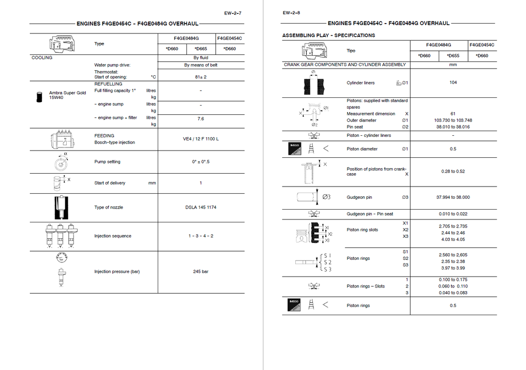
- Cures Destructive Thermal Overheating: Pinpoint cooling system breakdowns scientifically. Exhaustive procedures force mechanics to test the thermostat in heated fluid to physically verify its exact start-of-opening threshold at precisely 81 ± 2 °C, instantly ruling out a sheared water pump impeller or blocked radiator flow.
Important Pre-Purchase Advisories
- Standalone Engine Architecture Volume: This specific document is a dedicated engine repair manual exclusively for the F4GE0454C and F4GE0484G diesel powerplants (Tier 2 applications). It deeply covers engine block machining, rotational assembly, and engine-mounted electrics. For diagnostics relating to the host machine's hydraulic pumps, chassis CAN-bus electronics, or undercarriage components, a separate machine-specific service manual is strictly required.
Table of Contents
- Diagnostics
- Engine won’t start
- Engine overheats
- Engine lacks power and works erratically
- Engine exhaust smoke black or dark grey
- Engine exhaust smoke grey (verging on white)
- Engine exhaust smoke light blue
- Engine knocks irregularly
- Engine stops
- Engine exceeds max. revs number
- Excessive or insufficient oil pressure
- Excessive fuel consumption
- Engine won’t stop
- Engine F4GE0454C - F4GE0484G Overhaul
- F4GE0454C Engine
- F4GE0484G Engines
- Coding of source engines
- Main engine features
- General engine features
- Assembling play - specifications
- Tightening torque
- Tools
- Graphic indications and symbols
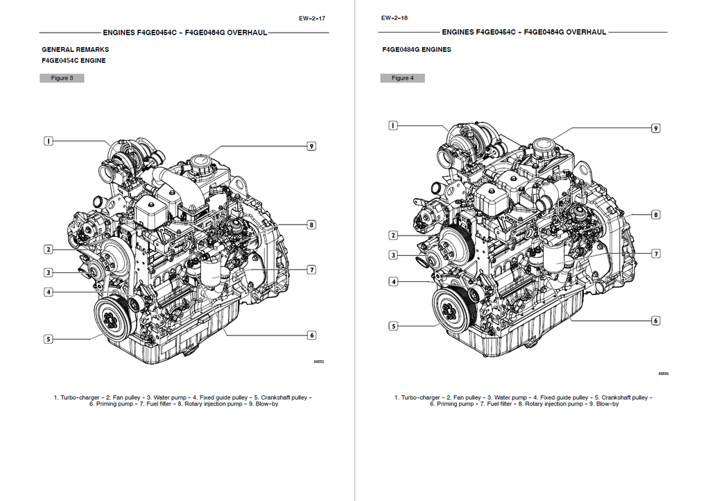
- General remarks
- F4GE0454C engine
- F4GE0484G engines
- Description of main mechanic engine components
- Crankcase
- Drive shaft
- Connecting rods
- Pistons
- Distributing shaft
- Valve control
- F4GE0454C engine cylinder head
- F4GE0484G engine cylinder head
- Valves and valve seats
- Valve guides
- Engine flywheel
- Auxiliary component drive
- Additional weights
- Lubrication
- Heat exchanger
- Oil pump
- Oil sump
- F4GE0484G *D660 / F4GE0454C * D660 Engines
- F4GE0484G *D665 Engine
- Oil vapour recirculation
- Cooling
- Water pump
- Fuel filter
- Mechanic injection feeding system
- Mechanic fuel pump
- Injection assembly
- Version F4GE0484G
- Engine bench-overhaul
- Disassembling the engine
- Replacing the seal ring
- Removing the injection pump
- Removing the rocker arm assembly
- Repair work on cylinder cluster
- Checks and measurements
- Checking the surface supporting the head on the cylinder cluster
- Checking the eccentric lift and the pin alignment
- Valve gear
- Distributing shaft
- Bushings
- Replacing the bushings
- Tappets
- Mounting the tappets – Distributing shaft
- Drive shaft
- Measuring the journals and crankpins
- Replacing the oil pump drive gears
- Mounting the main bearings
- Measuring the journal assembling play
- Checking the drive shaft shoulder play
- Connecting rod-piston assembly
- Pistons
- Measuring the piston diameter
- Gudgeon pins
- Conditions for correct pin/piston matching
- Piston rings
- Connecting rods
- Bushings
- Checking the connecting rods
- Checking the torsion
- Checking the flexion
- Mounting the connecting rod-piston assembly
- Connecting rod-piston match
- Mounting the piston rings
- Mounting the connecting rod/piston assemblies in the cylinder liners
- Measuring the crankpin assembling play
- Valve gear
- Distribution gearbox case
- Checking piston protrusion
- Valve timing
- Injection pump – 1st phase
- Timing
- Assembly of additional masses
- Timing of additional masses
- Flywheel cover case
- Engine flywheel
- Replacing the engine flywheel ring gear
- Injection pump – 2nd phase
- Mounting the injection pump – 2nd phase
- Mounting the oil and water pumps
- Mounting the water / oil heat exchanger
- Cylinder head
- Removing the valves
- Checking the cylinder head supporting surface
- Checking the cylinder head water seal
- Valve descaling, check and grinding
- Valves
- Valve seats
- Valve seat reconditioning - replacement
- Valve guide
- Checking the play between the valve stem, valve guide and valve centring
- Mounting the cylinder head
- Valve springs
- Rocker arm assembly
- Reattaching the cylinder head
- Mounting the injectors
- Replacing the injectors
- Removal
- Reassembling
- Rocker arm removal/reassembling
- Removal
- Reassembling
- Adjusting the tappets
- Recharge and start-up
- Starter motor
- Quick diagnosis
- Bosch 24 V - 4 kW
- Alternator
- Quick diagnosis
- Starter motor