

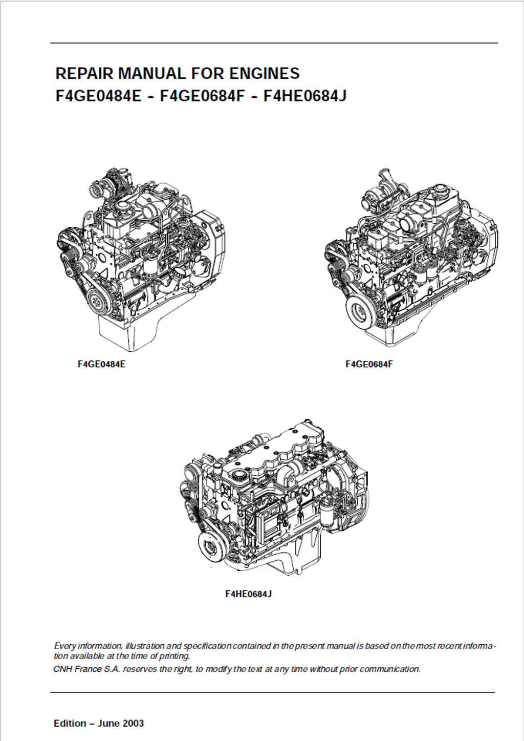

Iveco Motors / FPT Industrial F4GE0484E, F4GE0684F, F4HE0684J Diesel Engine Repair Manual 9-88930 English
Official Manual Overview
Take absolute command over the F4GE0484E (4.5L), F4GE0684F (6.7L), and the advanced Common Rail F4HE0684J (6.7L) Diesel Engines with this definitive OEM Repair Manual published under the CNH/CASE Construction architecture. Specifically engineered for heavy-duty earthmovers and wheeled loaders (such as the 521D, 621D, and 721D series), this uncompromising volume bypasses superficial maintenance to deliver dealership-level teardown and metrology protocols. It mandates absolute mathematical precision for the bottom-end rotational mass, enforcing strict 0.250 mm and 0.500 mm crankshaft reduction classes alongside highly controlled main bearing clearances (0.041 to 0.119 mm). Furthermore, it establishes brutal structural fastening matrices—requiring an intense multi-stage angular tightening sequence for the M12 cylinder head bolts (peaking at 70 Nm followed by a double 90-degree plastic-region stretch). Whether you are calibrating the Bosch VE4 / VE6 mechanical injection pumps with a rigid 0° ± 0.5° timing, or diagnosing the high-pressure fuel delivery network on the 145 kW F4HE0684J variant, this master reference provides the exact factory blueprints required to eradicate compression loss and restore peak industrial efficiency.
- Brands: Iveco Motors / FPT Industrial / CASE Construction
- Equipment Type: Diesel Engine
- Manuals Type: Repair Manual
- Machine Model: F4GE0484E, F4GE0684F, F4HE0684J
- Serial Number: N/R
- Region: N/R
- Book Code: 9-88930
- Issued: CNH France S.A. June 2003
- Language: English
- Pages: 258
- File Format: PDF (Searchable)
Core Selling Points
- Surgical Cylinder Head Metrology: Take the guesswork out of upper-end resurfacing and valvetrain sealing. This manual establishes absolute machining limits for the cylinder head, condemning the block if material removal exceeds the strict 0.13 mm threshold beyond the nominal baseline. Furthermore, it demands meticulous valve-to-guide operating clearances, strictly enforcing a 0.043 to 0.092 mm tolerance for the F4HE0684J variant to ensure flawless combustion chamber integrity under peak load.
- Heavy-Duty Bottom End Fastening Architecture: Secure the engine's reciprocating mass against catastrophic industrial compression. The documentation details highly complex multi-stage angular tightening sequences for the lower block, instructing builders to lock down the bed caps with an initial 50 ± 6 Nm base torque, followed by an 80 ± 6 Nm step, and culminating in a brutal 90° rotational stretch. The connecting rod caps demand equal precision, requiring a sequential 30 ± 5 Nm, 50 ± 5 Nm, and a final 60° plastic-region yield.
- Common Rail Circuitry & High-Pressure Blueprinting: Master the advanced electronic fuel delivery network of the Tier 2 F4HE0684J engine. The literature maps out the complete hydraulic logic of the high-pressure system, defining the exact parameters of the 5 bar high-pressure pump limiting valve and the 1.3 to 2 bar return regulating valve. It completely breaks down the internal operating principle of the proportional PWM pressure regulator and the pumping element supply ducts to prevent erratic atomization.
Features & Highlights
- Dynamic Valve Spring Calibration: Evaluate the overhead mechanisms utilizing strict factory load-testing standards. The guide instructs machinists to verify spring elasticity using tool 380000976, demanding that a healthy spring must maintain exactly 329 N of resistance at a 49.02 mm compression height, and peak at 641 N when compressed to 38.20 mm.
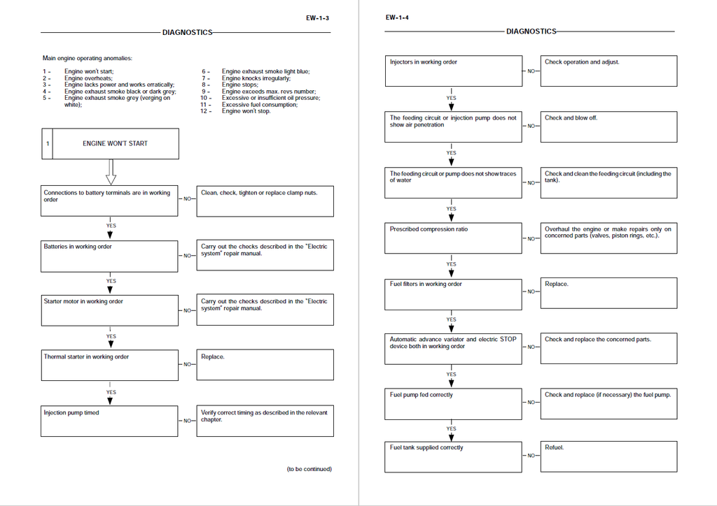
- Systematic Symptom Flowcharts: Navigate complex operational failures with highly logical diagnostic matrices. Dedicated troubleshooting trees isolate 12 critical anomalies—such as "Engine lacks power" or "Exhaust smoke black"—using sequential pathways that guide technicians to accurately test LDA device adjustments, injection pump timing, and cylinder compression using the specialized Motometer 75301430 adapter.
- Auxiliary Electrical Bench Diagnostics: Bypass parts-cannon troubleshooting on engine-mounted electrics. The manual provides specific testing protocols for the starting system, allowing mechanics to isolate an "insufficient dragging torque" fault directly to a short-circuited field winding, worn brushes, or a faulty electro-magnet before needlessly replacing the entire starter motor assembly.
Problem Solver
- Eradicates Destructive Bottom-End Knocking: Differentiate between upper valvetrain clatter and catastrophic lower-block failure instantly. The text equips technicians with the precise data to measure crankpin clearances (condemning the assembly if it falls outside the tight 0.033 to 0.041 mm window) and requires the camshaft end float to be verified at exactly 0.23 ± 0.13 mm to restore absolute rotational stability.
- Cures Phantom Fuel Overpressure & Idling Surges: Troubleshoot the modern Common Rail system scientifically. By referencing the exact hydraulic flow diagrams, technicians can trace fuel drainage routes from the electro-injectors back to the high-pressure pump, diagnosing internal regulator bypass faults that cause the ECU to command improper rail pressures.
- Resolves Severe Valvetrain Clatter: Prevent hidden upper-head destruction and restore breathing efficiency. Machinists are provided with absolute geometric data to physically recut the intake and exhaust seats using the specialized 380000975 grinder, restoring the exact 45° or 60° factory angles while enforcing a critical 0.024 to 0.377 mm operating play for the rocker arm shaft.
Important Pre-Purchase Advisories
- Strictly Engine-Focused Literature: This specific repair manual serves as the definitive technical blueprint exclusively for the standalone F4GE0484E, F4GE0684F, and F4HE0684J diesel engines. It exhaustively covers internal engine block machining, rotational assembly tolerances, mechanical pump timing, and common-rail fuel system breakdowns. For diagnostics relating to the host earthmover's main hydraulic pumps, chassis CAN-bus electronics, cab wiring schematics, or transmission teardowns, a separate machine-specific chassis manual is strictly required.
Table of Contents
- Diagnostics
- Engine won’t start
- Engine overheats
- Engine lacks power and works erratically
- Engine exhaust smoke black or dark grey
- Engine exhaust smoke grey (verging on white)
- Engine exhaust smoke light blue
- Engine knocks irregularly
- Engine stops
- Engine exceeds max. revs number
- Excessive or insufficient oil pressure
- Excessive fuel consumption
- Engine won’t stop
- Engine F4GE0484E Overhaul
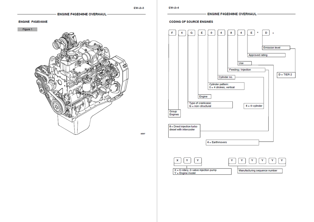
- Coding of source engines
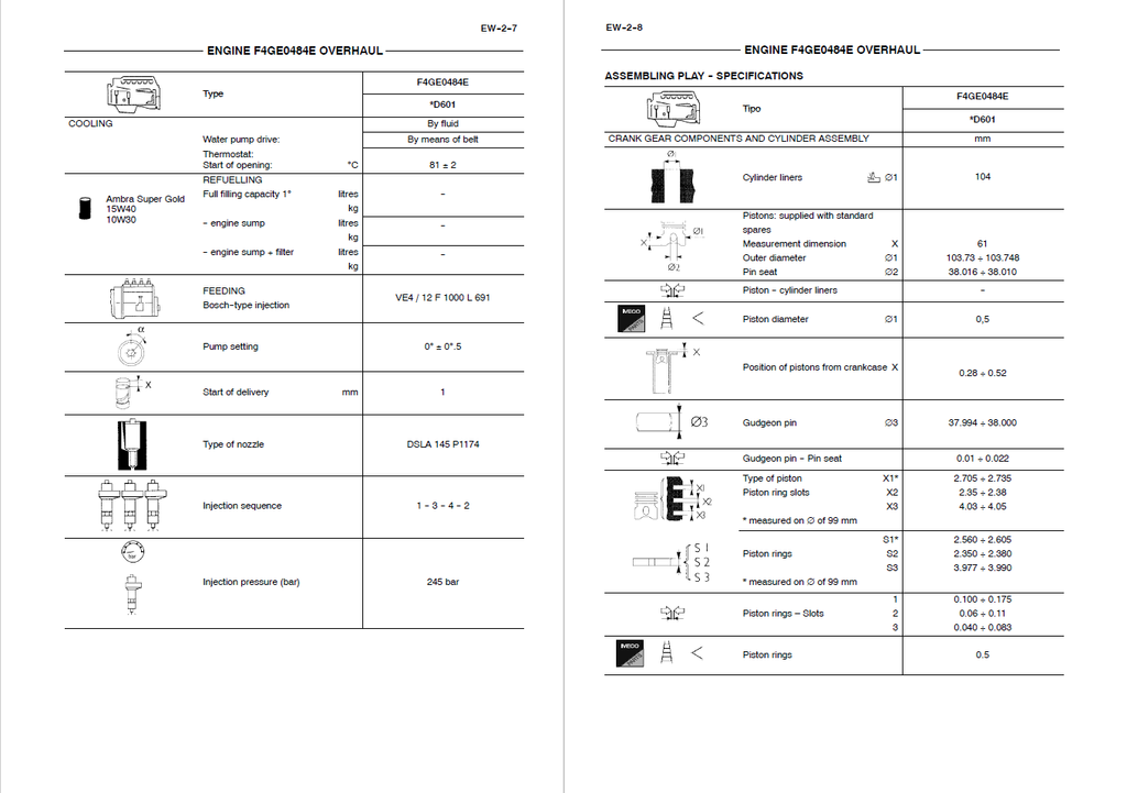
- Main engine features
- General engine features
- Assembling play - specifications
- Tightening torque
- Tools
- Graphic indications and symbols
- General remarks
- Description of main mechanic engine components
- Crankcase
- Drive shaft
- Drive shaft seal rings
- Connecting rods
- Pistons
- Distributing shaft
- Valve control
- Cylinder head
- Valves and valve seats
- Valve guides
- Engine flywheel
- Auxiliary component drive
- Lubrication
- Heat exchanger
- Oil pump
- Oil sump
- Oil vapour recirculation
- Cooling
- Water pump
- Mechanic injection feeding system
- Fuel prefilter
- Fuel filter
- Mechanic fuel pump
- Injection assembly
- Engine bench-overhaul
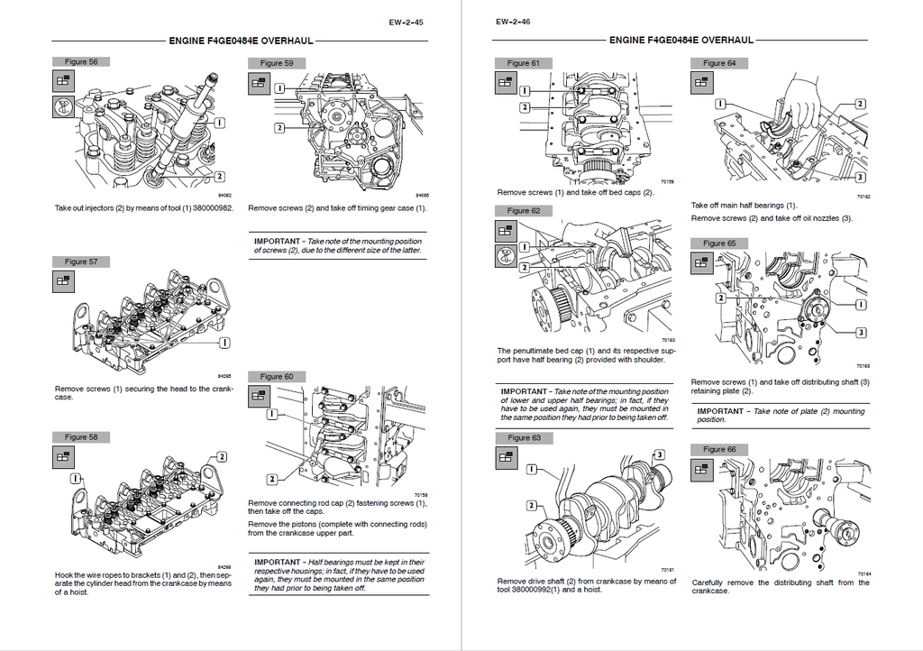
- Disassembling the engine
- Replacing the seal ring
- Removing the injection pump
- Removing the rocker arm assembly
- Repair work on cylinder cluster
- Checks and measurements
- Checking the surface supporting the head on the cylinder cluster
- Checking the eccentric lift and the pin alignment
- Valve gear
- Distributing shaft
- Bushing
- Replacing the bushings
- Tappets
- Mounting the tappets – Distributing shaft
- Drive shaft
- Measuring the journals and crankpins
- Replacing the oil pump drive gears
- Mounting the main bearings
- Measuring the journal assembling play
- Checking the drive shaft shoulder play
- Connecting rod-piston assembly
- Pistons
- Measuring the piston diameter
- Gudgeon pins
- Conditions for correct pin/piston matching
- Piston rings
- Connecting rods
- Bushings
- Checking the connecting rods
- Checking the torsion
- Checking the flexion
- Mounting the connecting rod-piston assembly
- Connecting rod-piston match
- Mounting the piston rings
- Mounting the connecting rod/piston assemblies in the cylinder liners
- Measuring the crankpin assembling play
- Checking piston protrusion
- Valve gear
- Distribution gearbox case
- Valve timing
- Injection pump – 1st phase
- Timing
- Flywheel cover case
- Engine flywheel
- Replacing the engine flywheel ring gear
- Injection pump – 2nd phase
- Mounting the injection pump – 2nd phase
- Mounting the oil and water pumps
- Mounting the water / oil heat exchanger
- Cylinder head
- Removing the valves
- Checking the cylinder head supporting surface
- Checking the cylinder head water seal
- Valves
- Valve descaling, check and grinding
- Checking the play between the valve stem, valve guide and valve centring
- Valve guide
- Valve seats
- Valve seat reconditioning - replacement
- Valve springs
- Mounting the cylinder head
- Reattaching the cylinder head
- Rocker arm assembly
- Mounting the injectors
- Replacing the injectors
- Removal
- Reassembling
- Rocker arm removal/reassembling
- Removal
- Reassembling
- Adjusting the tappets
- Valve timing
- Engines F4GE0684F -- F4HE0684J Overhaul
- Engine coding
- Main engine features
- Assembling play / specifications
- Tightening torque
- Tools
- Graphic indications and symbols
- General remarks
- Engine F4GE0684F
- Engine F4HE0684J
- Description of main mechanic engine components
- Crankcase
- Drive shaft
- Drive shaft seal rings
- Connecting rods
- Pistons
- Distributing shaft
- Engine F4GE0684F valve control
- Engine F4HE0684J valve control
- Engine F4GE0684F cylinder head
- Engine F4GE0684F valves and valve seats
- Engine F4HE0684J valves and valve seats
- Engine F4GE0684F valve guides
- Engine F4HE0684J valve guides
- Ponticelli comando valvole motore F4HE0684J
- Rettifica della testa motore F4HE0684J
- Engine flywheel
- Engine F4GE0684F auxiliary component drive
- Engine F4HE0684J auxiliary component drive
- Engine F4GE0684F Lubrication
- Engine F4HE0684J Lubrication
- Heat exchanger
- Oil pump
- Engine F4GE0684F oil sump
- Engine F4HE0684J oil sump
- Engine F4GE0684F oil vapour recirculation
- Engine F4HE0684J oil vapour recirculation
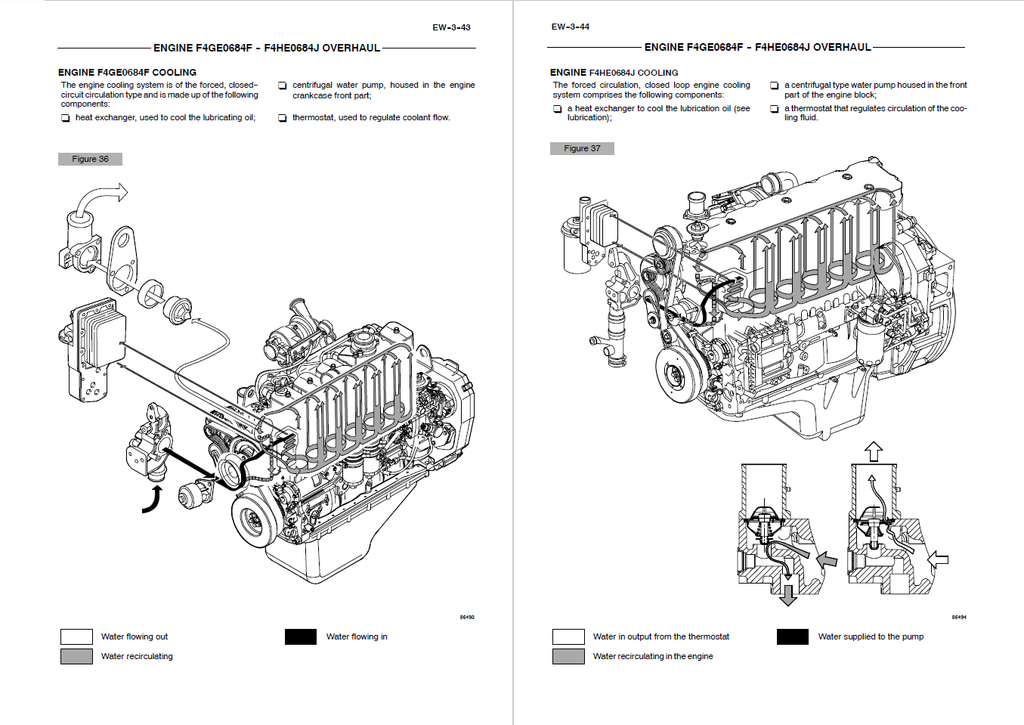
- Engine F4GE0684F cooling
- Engine F4HE0684J cooling
- Water pump
- Engine F4GE0684F mechanic injection feeding system
- Fuel prefilter
- Fuel filters
- Mechanic fuel pump
- Engine F4GE0684F Injection assembly
- Engine F4HE0684J fuel supply system
- Engine F4HE0684J fuel system diagram
- Fuel prefilter
- Fuel filter
- Mechanical feed pump
- Normal operating condition
- Outlet overpressure condition
- Bleed conditions
- High pressure pump
- Operating principle
- Engine F4GE0684F bench-overhaul
- Disassembling the engine
- Replacing the seal ring
- Removing the injection pump
- Removing the rocker arm assembly
- Repair work on cylinder cluster
- Checks and measurements
- Checking the surface supporting the head on the cylinder cluster
- Valve gear
- Distributing shaft
- Checking the eccentric lift and the pin alignment
- Bushings
- Replacing the bushings
- Tappets
- Mounting the tappets – Distributing shaft
- Drive shaft
- Measuring the journals and crankpins
- Replacing the oil pump drive gears
- Mounting the main bearings
- Measuring the journal assembling play
- Checking the drive shaft shoulder play
- Connecting rod-piston assembly
- Pistons
- Measuring the piston diameter
- Gudgeon pins
- Conditions for correct pin/piston matching
- Piston rings
- Connecting rods
- Bushings
- Checking the connecting rods
- Checking the torsion
- Checking the flexion
- Mounting the connecting rod-piston assembly
- Connecting rod-piston match
- Mounting the piston rings
- Mounting the connecting rod/piston assemblies in the cylinder liners
- Measuring the crankpin assembling play
- Checking piston protrusion
- Valve gear
- Distribution gearbox case
- Valve timing
- Injection pump – 1st phase
- Timing
- Flywheel cover case
- Engine flywheel
- Replacing the engine flywheel ring gear
- Injection pump – 2nd phase
- Mounting the injection pump – 2nd phase
- Mounting the oil and water pumps
- Mounting the oil sump
- Mounting the water / oil heat exchanger
- Cylinder head
- Removing the valves
- Checking the cylinder head supporting surface
- Checking the cylinder head water seal
- Valves
- Valve descaling, check and grinding
- Checking the play between the valve stem, valve guide and valve centring
- Valve guide
- Valve seats
- Valve seat reconditioning - replacement
- Valve springs
- Mounting the cylinder head
- Reattaching the cylinder head
- Rocker arm assembly
- Mounting the injectors
- Replacing the injectors
- Removal
- Reassembling
- Adjusting the tappets
- Rocker arm removal/reassembling
- Removal
- Reassembling
- Valve timing
- Revisione motore al banco F4HE0684J
- Disassembly of the engine
- Repair interventions
- Cylinder group
- Controls and measurements
- Cam lift check and pin alignment check
- Bushes
- Head face check on the cylinder group
- Timing system
- Camshaft
- Bush replacement
- Tappets
- Fitting tappets – camshaft
- Output shaft
- Measuring journals and crankpins
- Replacing oil pump control gear
- Fitting main bearings
- Finding journal clearance
- Checking output shaft shoulder clearance
- Connecting rod - piston assembly
- Pistons
- Measuring piston diameter
- Perni stantuffi
- Conditions for proper pin-piston coupling
- Split rings
- Connecting rods
- Bushes
- Checking torsion
- Checking connecting rods
- Checking bending
- Fitting connecting rod-piston assembly
- Connecting rod-piston coupling
- Fitting split rings
- Fitting connecting rod-piston assembly into cylinder barrels
- Finding crankpin clearance
- Checking piston protrusion
- Timing
- Flywheel housin
- Engine flywheel
- Replacing engine flywheel ring gear
- Cylinder head
- Removing the valves
- Removing carbon deposits, checking and grinding valves
- Checking cylinder head supporting surface
- Valves
- Removing carbon deposits, checking and grinding valves
- Checking clearance between valve stem and valve guide and valve centering
- Valve guide
- Valve seats
- Regrinding – replacing the valve seats
- Valve springs
- Fitting cylinder head
- Refitting the cylinder head
- Fitting injectors
- Rods
- Rocker assembly
- Tappet clearance adjustment
- Supporto cablaggio
- Recharging and start-up